

Digital camera interface
a digital camera and interface technology, applied in the field of interfaces, can solve the problems of inconvenient use, inability to meet the needs of automotive applications, and the speed of most technologies, and the tendency of camera links to be relatively expensiv
- Summary
- Abstract
- Description
- Claims
- Application Information
AI Technical Summary
Benefits of technology
Problems solved by technology
Method used
Image

Examples
Embodiment Construction
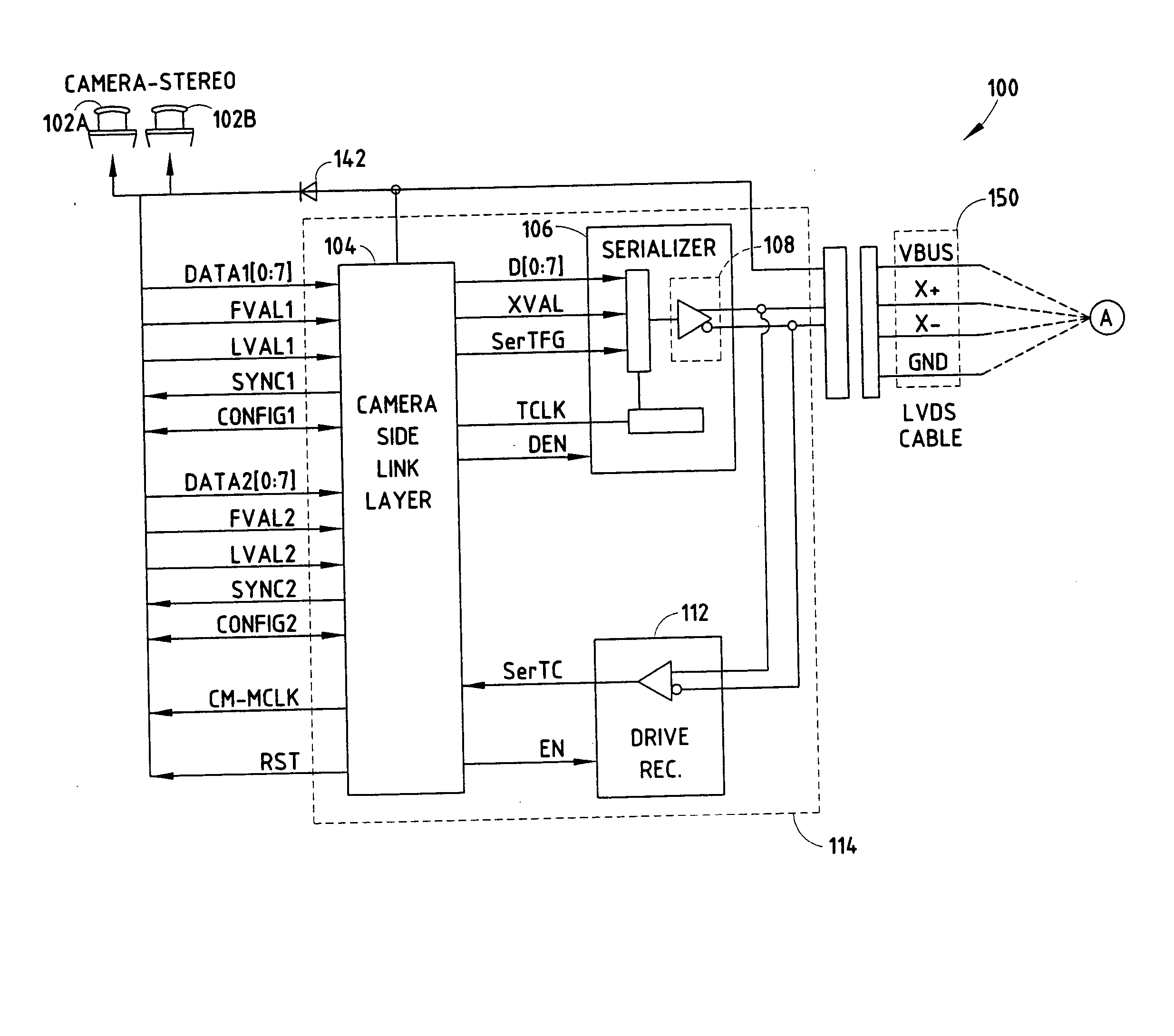
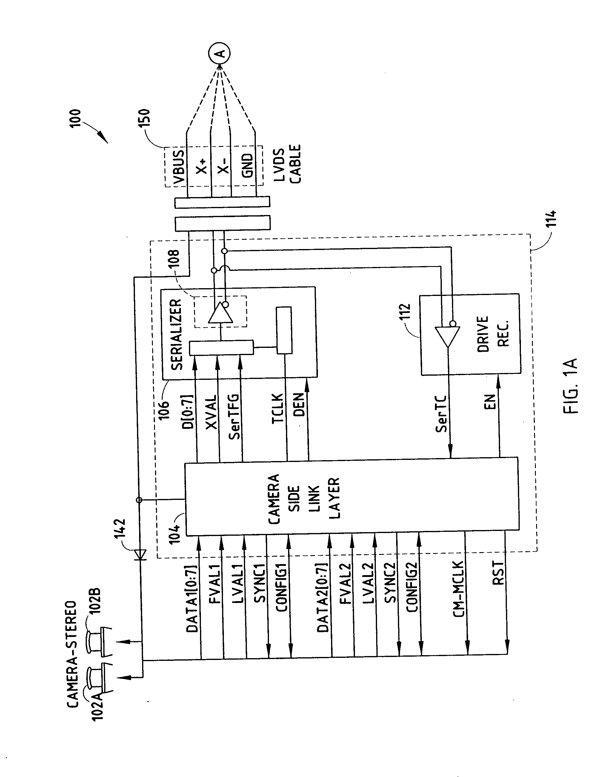
[0016] According to the present invention, a low-cost, high-performance host processor to camera interface is disclosed herein. In its basic embodiment, the host processor to camera interface includes a camera side interface that is coupled by a cable to a host processor side interface. The camera side interface includes a camera side link layer coupled to a camera, with the camera providing video data and the camera side link layer converting the video data to a desired video data format. The camera side interface also includes a serializer coupled to the camera side link layer for serializing the video data in the desired video data format. A camera side transmitter that is coupled to the serializer transmits the serialized video data to the host processor side interface, via the cable.
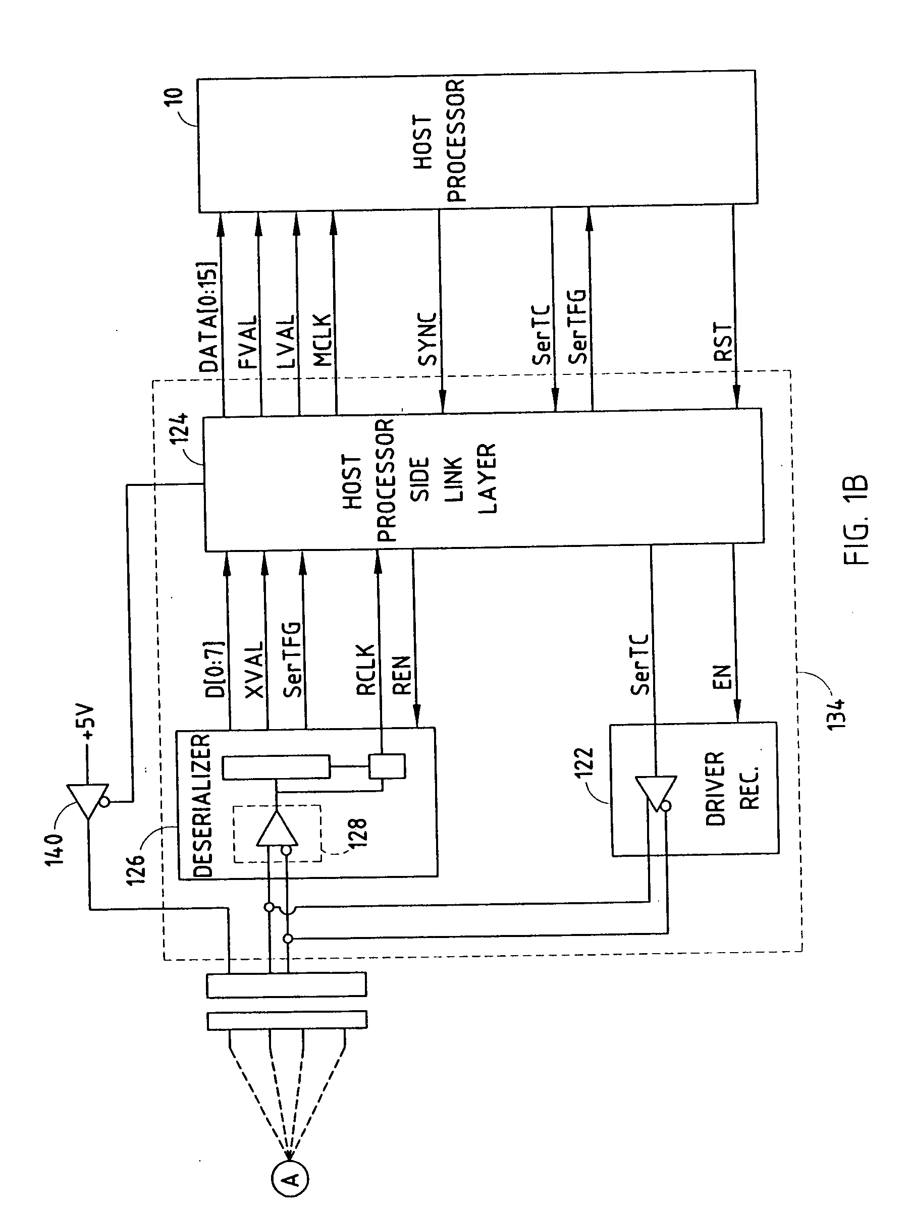
[0017] The host processor side interface includes a host processor side receiver, a deserializer and a host processor side link layer. The host processor side receiver receives serialized video dat...
PUM
 Abstract
Description
Claims
Application Information