Color correction method for an imaging system

a color correction and imaging system technology, applied in the field of imaging systems, can solve problems such as color shift, and achieve the effects of reducing memory storage requirements, minimizing color correction complexity, and reducing storage requirements

Inactive Publication Date: 2005-04-07
LEXMARK INT INC
View PDF28 Cites 88 Cited by
  • Summary
  • Abstract
  • Description
  • Claims
  • Application Information

AI Technical Summary

Benefits of technology

An advantage of certain embodiments of the present invention is the ability to render consistent color for an imaging system without regard to manufacturing variations in printing cartridges and scanners, and without regard to variations in substrates.
Another advantage of certain embodiments is reduced memory storage requirements, by storing only a signature color data lookup table or a class code corresponding to a signature color data lookup table, rather than a complete color conversion lookup table, for performing color correction.
Yet another advantage of certain embodiments is to reduce storage requirements and minimize color correction complexity by employing only a limited number of signature color data lookup tables as classes of color correction for use with a large number of printing cartridges, scanner, and substrates.

Problems solved by technology

However, in color reproduction, a common problem that occurs is color shift due to variations in components of a color reproduction system.
In addition, color reproduction systems may have significant color shifts between one factory-calibrated substrate and an un-calibrated substrate, or between one un-calibrated substrate and another un-calibrated substrate.

Method used


Image

  • Color correction method for an imaging system
  • Color correction method for an imaging system
  • Color correction method for an imaging system

Examples


Embodiment Construction

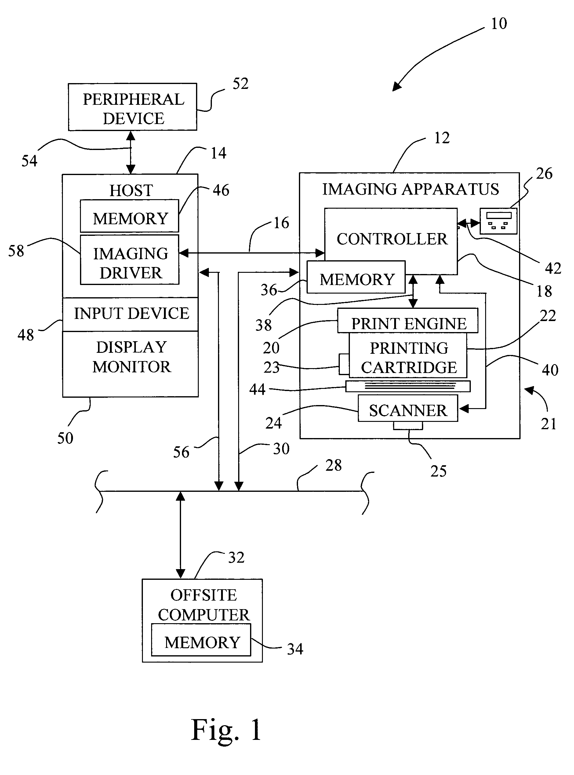
Referring now to the drawings, and particularly to FIG. 1, there is shown a diagrammatic depiction of an imaging system 10 embodying the present invention. Imaging system 10 includes an imaging apparatus 12 and a host 14. Imaging apparatus 12 communicates with host 14 via a communications link 16.

Imaging apparatus 12 can be, for example, an ink jet printer and / or copier, an electrophotographic printer and / or copier, or an all-in-one (AIO) unit that includes a printer, a scanner, and possibly a fax unit. As an AIO unit, imaging apparatus 12 includes a controller 18, a print engine 20, and one or more of an imaging object 21, such as a printing cartridge 22 having cartridge memory 23 and a scanner 24 having scanner memory 25, and a user interface 26. Imaging apparatus 12 has access to a network 28, such as the Internet, via a communication line 30, to interface with an offsite computer 32 having an offsite memory 34, in order to transmit and / or receive data for use in carrying out ...


PUM

PropertyMeasurementUnit
color shiftaaaaaaaaaa
coloraaaaaaaaaa
color similarityaaaaaaaaaa

Abstract

A method for correcting color shift in an imaging system, including an imaging object, and a standard color conversion lookup table associated with the imaging object, includes measuring a plurality of test patches to obtain color data associated with the imaging object. A signature color data lookup table is generated, based on the color data, and is combined with the standard color conversion lookup table to generate a composite color conversion lookup table for use with the imaging object.

Description

BACKGROUND OF THE INVENTION 1. Field of the Invention The present invention relates to an imaging system, and, more particularly, to a method for correcting color shift in an imaging system that occurs due to variations in printing cartridges, scanners, and / or substrates and the like. 2. Description of the Related Art In recent years, the use of computers for home and business purposes has increased significantly. Computer systems typically incorporate a computer monitor, a scanner, and a printer. Users frequently employ such systems for scanning, modifying, and / or creating various color documents. The documents may include personal greeting cards, photographs, pamphlets, flyers, brochures, business presentations, business cards, and other personal or business related documents. Such color documents are usually reproduced on a substrate using a personal or business printer, and distributed to various recipients, such as family or friends, or individual / business consumers. During...

Claims


Application Information

Patent Timeline
Patent Type & Authority Applications(United States)
IPC IPC(8): G03F3/08G06F15/00H04N1/60
CPCH04N1/6033
Inventor DEER, ANNA Y.HUANG, XUAN CHAONYSTROM, BRANT D.REEL, RICHARD L.
Owner LEXMARK INT INC
Why Eureka
Try Eureka