Combination of inverter casing and heat sink member

a technology of inverter and heat sink, which is applied in the direction of electrical apparatus casings/cabinets/drawers, gaseous cathodes, substation/switching arrangement casings, etc., can solve the problems of overheating and increase manufacturing costs, and achieve better heat dispensing efficiency and a larger area

Inactive Publication Date: 2008-04-15
COTEK ELECTRONICS INDAL
View PDF9 Cites 18 Cited by
  • Summary
  • Abstract
  • Description
  • Claims
  • Application Information

AI Technical Summary

Benefits of technology

[0008]The main object of the present invention is to provide a casing of a power supply with at least one heat sink element in which the casing having a top part, a base and two sidewalls. The top part, the base and the two sidewalls are integrally manufactured as a one piece such that the heat from the electronic parts inside the casing can be sent to the casing which has a larger area for dispensing heat. Thus, the casing of the power supply with at least one heat sink element could provide better heat dispensing efficiency.
[0009]Another object of the present invention is to provide a casing of a power supply with at least one heat sink element in which the top part, the base and the two sidewalls are integrally manufactured as a one piece. The electronic parts is positioned by a heat sink member, and the front and rear sides of the electronic part are in contact with the casing and the heat sink member, such that heat can be dispensed efficiently.
[0010]Another object of the present invention is to provide a casing of a power supply with at least one heat sink element which is manufactured integrally as a one piece so that the manufacturing cost is reduced and the color of the casing is consistent.
[0011]Another object of the present invention is to provide a casing of a power supply with at least one heat sink element wherein the casing is manufactured integrally as a one piece by way of aluminum extrusion which improves heat dispensing efficiency and electro-magnetic wave leakage.

Problems solved by technology

However, the casing 100 is composed of the top part 110 and the base 120, so that the top part 110 and the base 120 have to be manufactured and coated with proper material in separate, this increases manufacturing cost.
The heat that the base 120 absorbs cannot be dispensed and sent to the top part 110, which might cause overheat problem during operation.

Method used


Image

  • Combination of inverter casing and heat sink member
  • Combination of inverter casing and heat sink member
  • Combination of inverter casing and heat sink member

Examples


Embodiment Construction

[0027]In the following detailed description of the present invention, numerous specific details are set forth in order to provide a thorough understanding of the present invention. However, it will be obvious to one skilled in the art that the present invention may be practiced without these specific details. In other instances well known methods, procedures, components, and circuits have not been described in detail so as not to unnecessarily obscure aspects of the present invention.

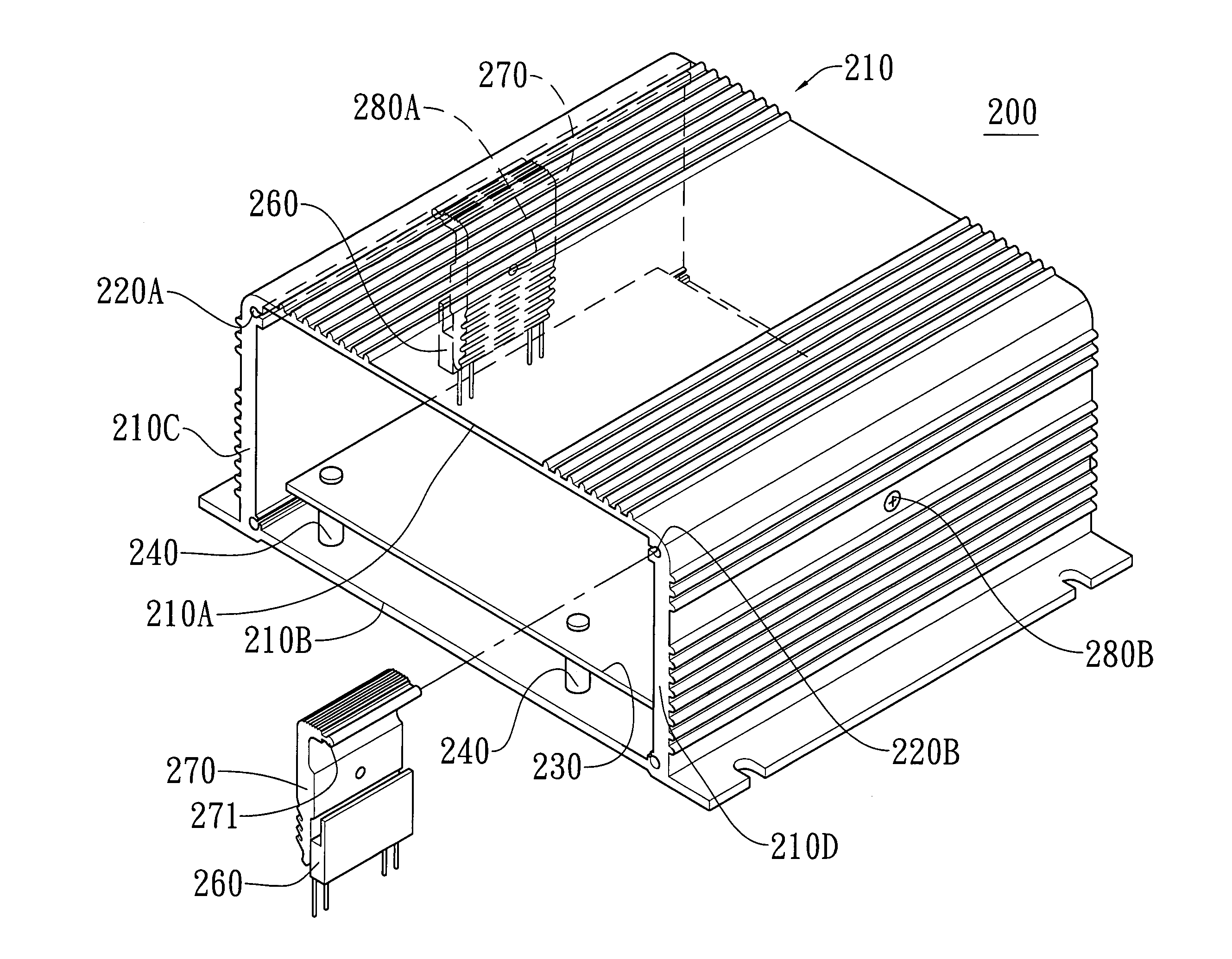
[0028]Referring to FIGS. 3, 4A and 4B, the DC / AC inverter 200 of the present invention comprises a casing 210 having a top part 210A, a base 210B and two sidewalls 210C, 210D. The top part 210A, the base 210B and the two sidewalls 210C, 210D are integrally manufactured as a one piece and the casing 210 has a hollow interior and an open side 250. A printed circuit board 230 is received in the casing 210 via the open side 250 and a plurality of electronic parts 260 are connected on the printed circuit boa...


PUM


Abstract

The present invention provides an inverter assembly which comprises a casing with a top part, a base and two sidewalls, and the top part. The base and the two sidewalls are integrally manufactured as a one-piece. A printed circuit board with a plurality of electronic parts is received in the casing. A heat sink member has a guide member and a body, wherein the guide member is slidably engaged with a groove defined in an inside of either of the two sidewalls is able to be pivoted about the guide member in a limited angle so as to adjust a gap between the inside of the sidewall and an inside of the heat sink member. The electronic part is clamped between the inside of the sidewall and an inside of the heat sink member. The front and rear sides of the electronic part are in contact with the heat sink member and the sidewall so as to efficiently dispense the heat.

Description

BACKGROUND OF THE PRESENT INVENTION[0001]1. Field of Invention[0002]The present invention relates to a casing of a power supply with at least one heat sink element, and more particularly to a casing of a DC / AC inverter with at least one heat sink element in which at least one electronic part is positioned and in contact with both the sidewall of the casing and the heat sink member so as to efficiently dispense heat from the electronic part.[0003]2. Description of Related Arts[0004]Please refer to FIG. 1, which is a schematic diagram of a conventional casing of a DC / AC inverter 100. As shown in FIG. 1, the conventional casing of the DC / AC inverter 100 generally comprises a top part 110 and a base 120 which is an individual part from the top part 110. A printed circuit board (PCB) 160 is positioned inside the conventional casing of the DC / AC inverter 100. The printed circuit board (PCB) 160 is positioned onto the base 120 by extending bolts through the printed circuit board 160 in the...

Claims


Application Information

Patent Timeline
Patent Type & Authority Patents(United States)
IPC IPC(8): H05K7/20
CPCH05K7/209
Inventor CHEN, WEI-KUANG
Owner COTEK ELECTRONICS INDAL
Why Eureka
Try Eureka