
Current monitoring system and method for metering peristaltic pump

Inactive Publication Date: 2005-04-07
JOHNSONDIVERSEY INC
View PDF7 Cites 12 Cited by
  • Summary
  • Abstract
  • Description
  • Claims
  • Application Information

AI Technical Summary

Benefits of technology

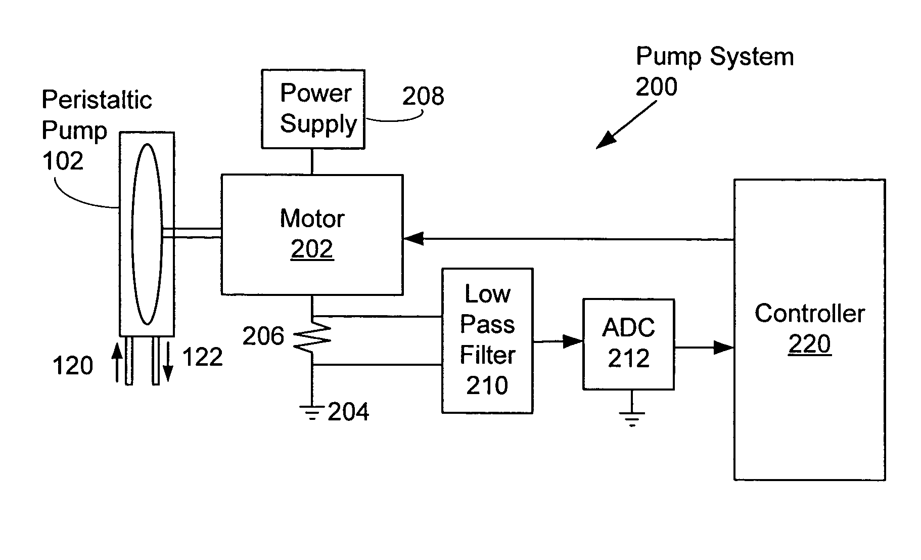
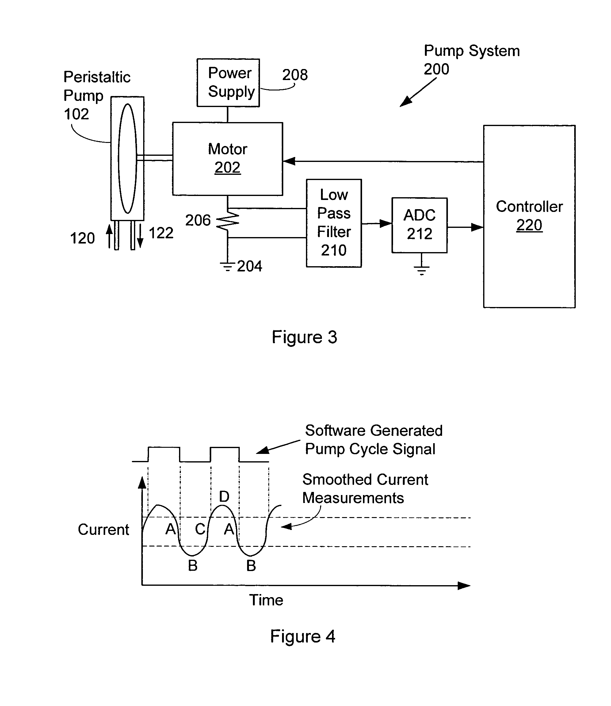
A pump system includes a peristaltic pump having a rotor, a motor and a controller. The motor is configured to drive the peristaltic pump so as to deliver a liquid product from a source to a receiving location. The controller monitors a drive current of the motor so as to track rotation of the pump's rotor. The controller counts units of rotation of the pump's rotor, and stops the motor when the counted units of rotation reach a specified target count value.

Problems solved by technology

Attempts to modify the pumps' run time based on a measurement of the battery voltage, so as to deliver a constant volume of product, have been largely unsuccessful.
Thus, the volume of product delivered is not well defined by the run time and battery voltage.

Method used


Image

  • Current monitoring system and method for metering peristaltic pump
  • Current monitoring system and method for metering peristaltic pump
  • Current monitoring system and method for metering peristaltic pump

Examples


Embodiment Construction

Theory of Operation

While a theory of operation is provided, it is to be understood that the invention is itself is the apparatus of the invention and the method of operation of the invention. The theory of operation is provided solely to make the apparatus and methods of the invention easier to understand.

FIGS. 2A, 2B, 2C and 2D show the tubing 114, rotor 110 and rollers 112 (112-A, 112-B) of a peristaltic pump, with the rotor and rollers in a sequence of four different positions as the pump rotor 110 turns clockwise. The rotor and rollers are sometimes called a pump head assembly or pump head. The number of rollers 112 on the rotor 110 may vary from one pump to another, and this number is typically 2, 3 or 4. The function of the rollers is to compress the tubing as the rotor rotates, and to thereby move product through the tubing from in the inlet 120 to the outlet 122. For purposes of explaining the theory of operation of the invention, we will explain the operation of a pump h...


PUM


Abstract

A pump system includes a peristaltic pump having a rotor, a motor and a controller. The motor is configured to drive the peristaltic pump so as to deliver a liquid product from a source to a receiving location. The controller monitors a drive current of the motor so as to track rotation of the pump's rotor. The controller counts units of rotation of the pump's rotor, and stops the motor when the counted units of rotation reach a specified target count value.

Description

FIELD OF THE INVENTION The present invention relates to the field of pumping devices and systems, and more particularly to systems and methods for measuring or metering the quantity of fluid pumped by a peristaltic pump. BACKGROUND OF THE INVENTION Referring to FIG. 1, a peristaltic pump 102 is typically used to deliver either water, or a liquid chemical or mixture, from a source 104 to a receiving device 106 (e.g., a dishwasher, or clothes washer). The peristaltic pump 102 has a rotor 110 (FIG. 2A) with rollers 112 (112-A and 112-B in the example shown in FIG. 2A) that compress a tube 114 as the rotor is rotated. The pump 102 is driven by a motor (not shown in FIG. 1), and liquid is drawn into the tube 114 (also called the tubing) at an inlet 120 and then forced through the tube to an outlet 122 by the rollers of the rotor as the rotor turns on its axis. Operation of the pump 102 is controlled by a controller 130, which typically runs the pump 102 for a fixed or specified amount ...

Claims


Application Information

Patent Timeline
IPC IPC(8): B67D7/30F04B43/12F04B49/06
CPCF04B43/1253F04B2203/0201F04B49/065
Inventor ANDERSON, THOMAS D.COCKING, ANDREW J.
Owner JOHNSONDIVERSEY INC
Features
  • Generate Ideas
  • Intellectual Property
  • Life Sciences
  • Materials
  • Tech Scout
  • Unparalleled Data Quality
  • Higher Quality Content
  • 60% Fewer Hallucinations
Learn More