Motor-driven injection molding apparatus

a motor-driven, injection molding technology, applied in the direction of ceramic shaping apparatus, food shaping, manufacturing tools, etc., can solve the problems of large-scale production of toggle-type molding apparatuses and high molding pressure, and achieve the effect of simple structure, reduced number of parts, and simple plate structur

Inactive Publication Date: 2005-04-07
DAIWA KASEI IND CO LTD
View PDF13 Cites 5 Cited by
  • Summary
  • Abstract
  • Description
  • Claims
  • Application Information

AI Technical Summary

Benefits of technology

The present invention relates to a motor-driven injection molding apparatus with improved structural simplicity and efficiency. By eliminating traditional tie bars and replacing them with a simpler design, fewer parts are needed, saving time and money during assembly. Additionally, the absence of certain components reduces the size requirements of the machine, allowing for increased flexibility in placement options. Furthermore, the detection of mold clamping strokes based on changes in electrical loads allows for accurate control without requiring expensive sensors. Finally, the inclusion of a plunger-in screw and a receiving hole results in faster and more efficient molding processes compared to standard screw designs.

Problems solved by technology

This patent describes an injection molding machine that has three main parts: a metal mold opening and closing mechanism for holding the molds in place, an injection mechanism for heating up and plasticizing the materials used for molding, and a driving system for moving all components. There are two types of metal mold openings and closing mechanisms - one uses a toggle action while another uses a direct hydraulic method.

Method used


Image

  • Motor-driven injection molding apparatus
  • Motor-driven injection molding apparatus
  • Motor-driven injection molding apparatus

Examples


Embodiment Construction

[0038] A description will be given below of an embodiment in accordance with the present invention with reference to the accompanying drawings.

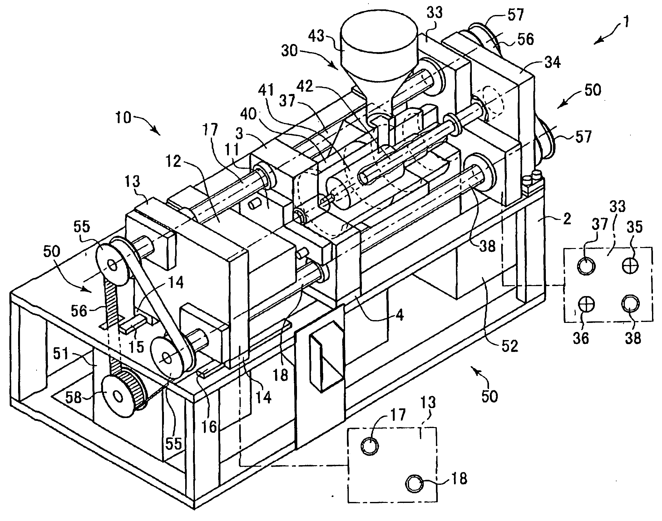
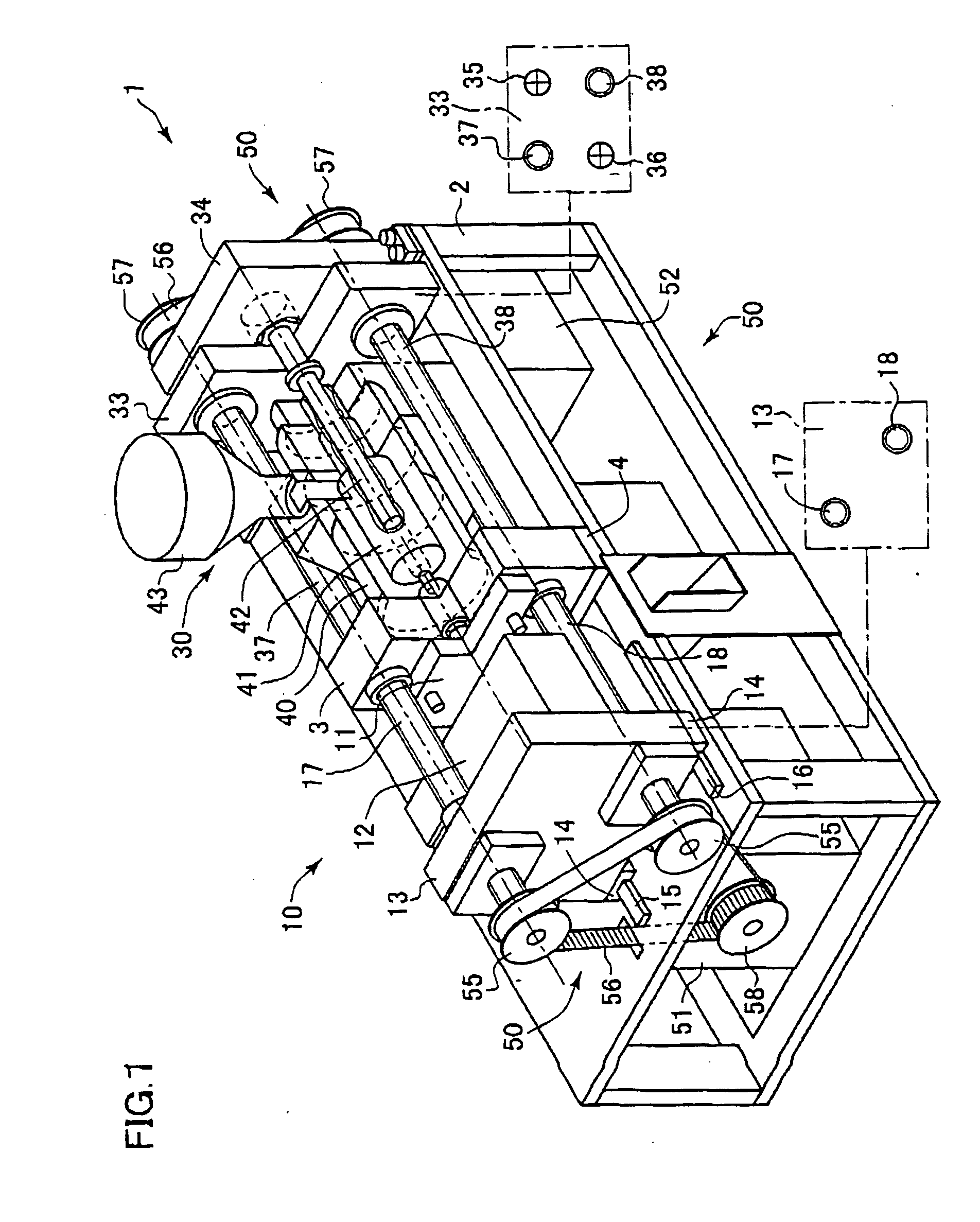
[0039] A motor-driven injection molding apparatus 1 (hereinafter, refer also to an apparatus) corresponding to an embodiment in accordance with the present invention shown in FIG. 1 has a frame 2 forming a base of the apparatus 1, a center fixed plate 3 provided in a center of the apparatus 1 and fixed to the frame 2 by a fixing portion 4, and a mold opening and closing mechanism portion 10 and an injection mechanism portion 30 separated on the border of the center fixed plate 3. Further, drive mechanism portions 50 and 50 for driving the mold opening and closing mechanism portion 10 and the injection mechanism portion 30 are provided in an inner portion of the frame 2 and in the periphery of the frame 2.

[0040] The mold opening and closing mechanism portion 10 is provided with the center fixed plate 3, and an opening and closing side movabl...


PUM

PropertyMeasurementUnit
Forceaaaaaaaaaa

Abstract

The invention provides a motor-driven injection molding apparatus in which an entire of the apparatus is simplified and made compact. In a motor-driven injection molding apparatus (1), a movable metal mold (12) clamped to a stationary metal mold (11) is mounted to a movable mold plate (13), and two ball screws (17, 18) for moving the movable mold plate (13) are passed through two points on opposing corners of the movable mold plate (13). End portions of the ball screws (17, 18) are set in a cantilever state, and are rotated via pulleys (55, 55) and a timing belt (56), thereby moving the movable mold plate (13). Further, the movable mold plate (13) is guided by a slide guide having a structure that a bearing unit (14) fixed to both sides of a lower portion thereof is fitted to linear rails (15, 16). On the other hand, in an injection side, a injection side movable plate (33) to which an injection plunger (42) is fixed by two tie bars (35, 36) and two ball screws (37, 38) on respective opposing corners, and the same slide guides as mentioned above moves. The movable mold plate (13) is moved by the opening and closing side ball screws (17, 18) so as to be mold clamped, and the injection side movable plate (33) is thereafter moved so as to inject.

Description


Claims


Application Information

Patent Timeline
Owner DAIWA KASEI IND CO LTD
Why Eureka
Try Eureka