

High coefficient woven friction material
a friction material and high coefficient technology, applied in the field of non-asbestos, non-metallic woven materials, can solve the problems of not being suitable for high-energy applications, and achieve the effect of durable friction material and high-performance us
- Summary
- Abstract
- Description
- Claims
- Application Information
AI Technical Summary
Benefits of technology
Problems solved by technology
Method used
Image

Examples
examples
[0091] Slip Clutch Interface Technology Requirements: The friction materials of the present invention are designed for slipping clutch applications that meet special requirements. These requirements include high mechanical strength, heat resistance, durability, stability and shudder resistance. The friction material of the present invention has high porosity, a unique material structure for high mechanical strength, high temperature conductivity, and anti-shudder friction modifier characteristics. These material characteristics are the necessary conditions of smooth slip torque output and long term friction stability.
[0092] The slip clutch material requirements for desirable slip torque response and long-term durability include good curve shape and long term friction stability. The good curve shape is dependent on high material porosity and high friction modifier content. The long term friction stability is dependent on high porosity, (anti-glazing) and high temperature ingredients...
example i
[0095] The torque curve shape indicates that the friction material of the present invention is especially useful in speed, high energy and high temperature application. The stable torque curve also shows that the friction material is noise free.
[0096] Table 1 shows the formulations for comparative examples A and B, and Examples 1 and 2 Table I also shows the basis weight, caliper, porosity, dry and wet tensile and ash properties for the examples shown. The new materials comprise a primary layer having an optimal amount of carbon fiber and a secondary layer comprises a mixture of carbon and celite and, optionally, a retention aid such as latex. In the secondary layer, in preferred embodiments, the ratio of carbon particles to silica ranges from about 1 to 4 to about 1 to 2.
TABLE ICompar.Compar.Furnish %Example 1 Example 2example AExample BPrimary LayerAramid fiber555520-254-0-6022.550Carbon fiber 2 mm101010-2015Cotton25-3531Graphite252515-2510-202115Silica101020-3015-2525.520Latex...
example ii
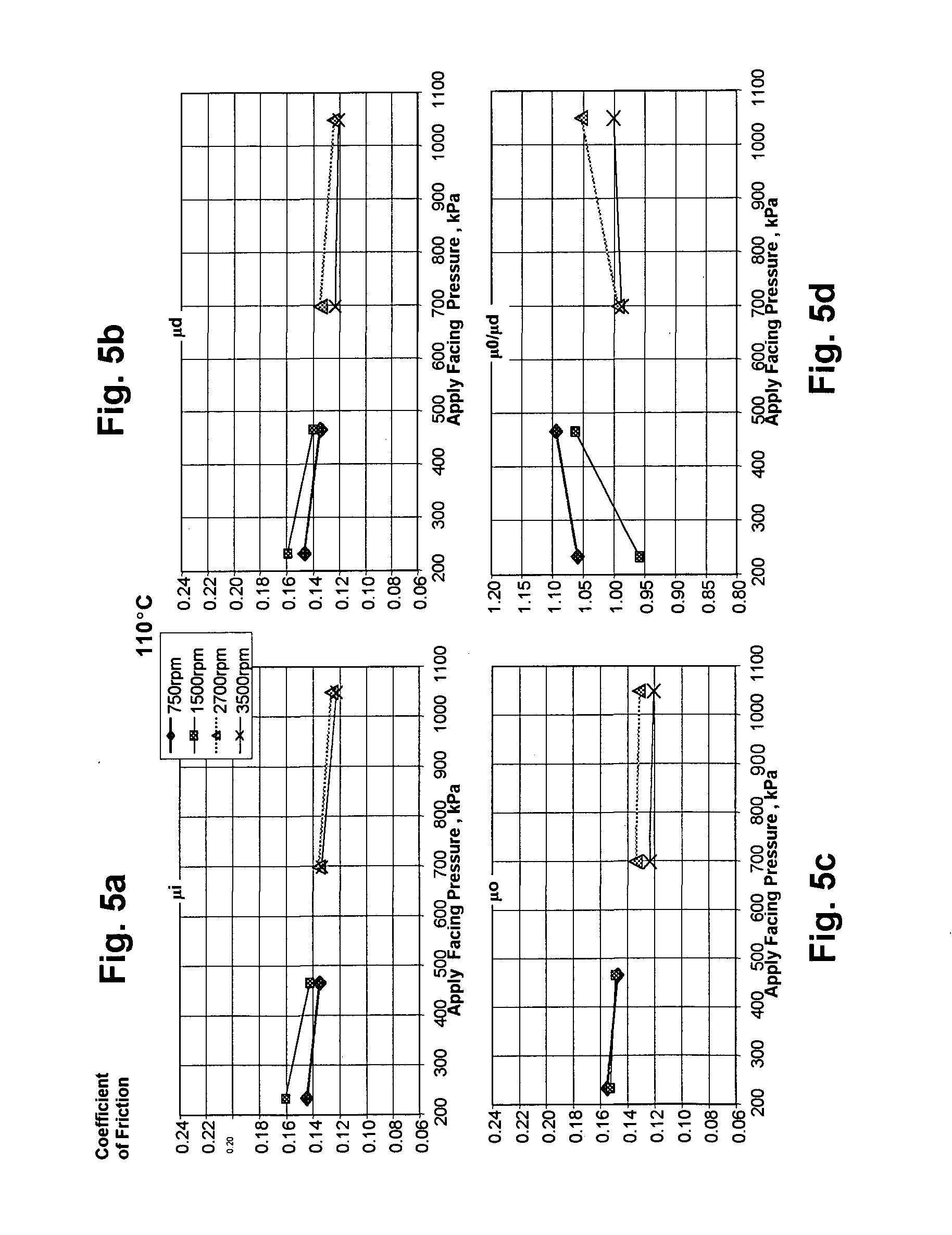
[0097] The μPVT torque curves provide further information about the materials of the present invention.
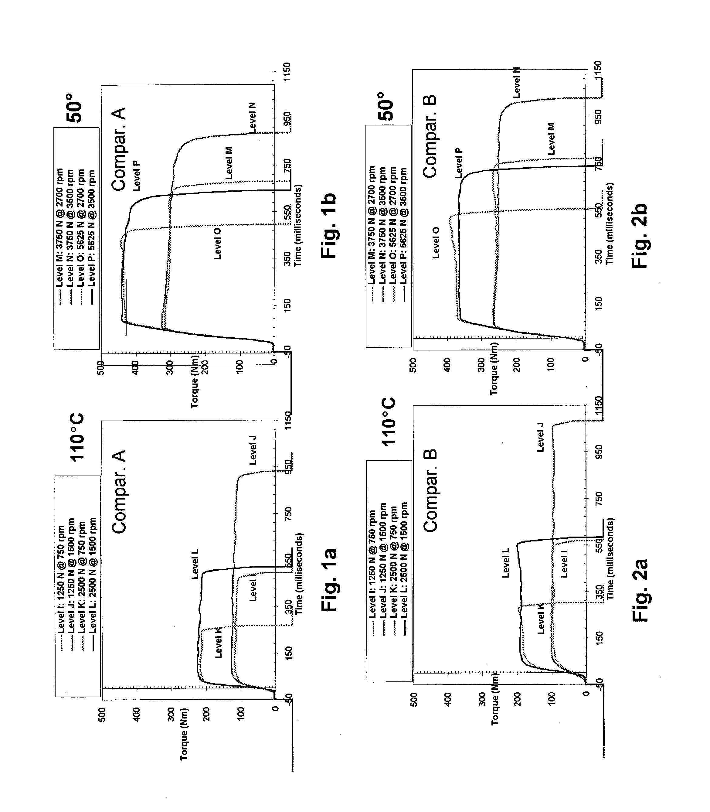
[0098]FIGS. 1a and 1b the torque curves (μPVT) for Comparative example A at various levels and speed at 100° C. (FIG. 1a) and at 50° C. (FIG. 1b).
[0099]FIGS. 2a and 2b the torque curves (μPVT) for Comparative example B at various levels and speed at 100° C. (FIG. 2a) and at 50° C. (FIG. 2b).
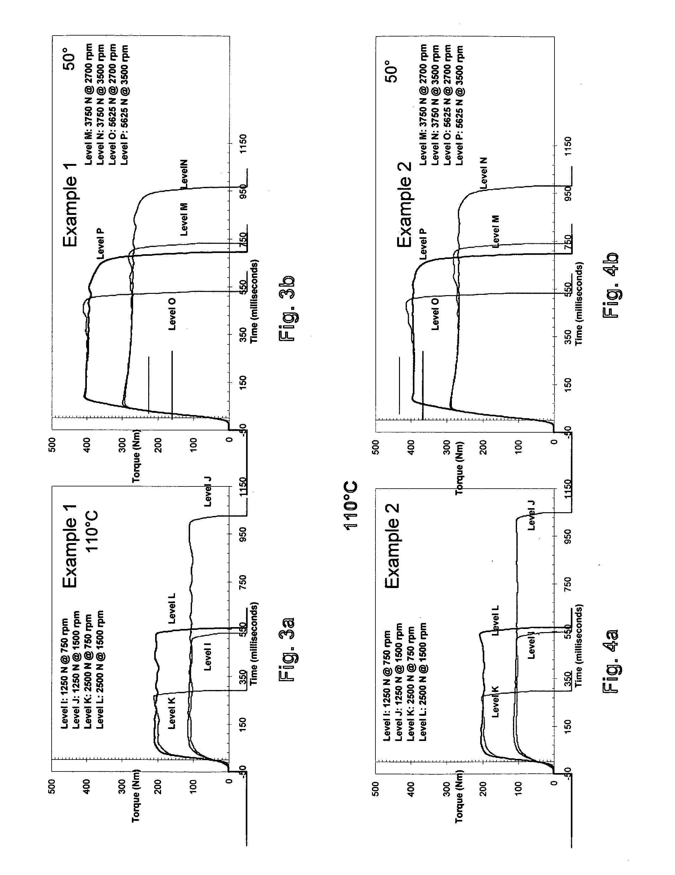
[0100]FIGS. 3a and 3b the torque curves (μPVT) for Example 1 at various levels and, speed at 100° C. (FIG. 3a) and at 50° C. (FIG. 3b). FIGS. 4a and 4b the torque curves (μPVT) for Example 2 at various levels and speed at 100° C. (FIG. 4a) and at 50° C. (FIG. 4b).
PUM
| Property | Measurement | Unit |
|---|---|---|
| Fraction | aaaaa | aaaaa |
| Fraction | aaaaa | aaaaa |
| Fraction | aaaaa | aaaaa |
Abstract
Description
Claims
Application Information