High coefficient friction material with symmetrical friction modifying particles

a technology of symmetrical friction and friction modification, applied in the field of non-asbestos, non-metallic materials, can solve the problems of not being suitable for high-energy applications, and achieve the effect of durable, high-performance friction materials

Inactive Publication Date: 2005-03-24
BORGWARNER INC
View PDF42 Cites 38 Cited by
  • Summary
  • Abstract
  • Description
  • Claims
  • Application Information

AI Technical Summary

Benefits of technology

[0040] The coated material can be impregnated using different resin systems. In certain embodiments, it is useful to impregnate the coated material with a phenolic resin or a modified phenolic-based resin. In certain embodiments, when a silicone resin is blended or mixed with a phenolic resin in compatible solvents and that silicone-phenolic resin blend is used to impregnate the coated material of the present invention, an especially useful high performance, durable friction material is formed.

Problems solved by technology

Both commercially available slip clutches, and transmission materials were investigated and proved not to be suitable for use in high energy applications.

Method used


Image

  • High coefficient friction material with symmetrical friction modifying particles
  • High coefficient friction material with symmetrical friction modifying particles
  • High coefficient friction material with symmetrical friction modifying particles

Examples


examples

[0116] Slip Clutch Interface Technology Requirements: The friction materials of the present invention are designed for slipping clutch applications that meet special requirements. These requirements include high mechanical strength, heat resistance, durability, stability and shudder resistance. The friction material of the present invention has high porosity, a unique material structure for high mechanical strength, high temperature conductivity, and anti-shudder friction modifier characteristics. These material characteristics are the necessary conditions of smooth slip torque output and long term friction stability.

[0117] The slip clutch material requirements for desirable slip torque response and long-term durability include good curve shape and long term friction stability. The good curve shape is dependent on high material porosity and high friction modifier content. The long term friction stability is dependent on high porosity (anti-glazing) and high temperature ingredients....

example i

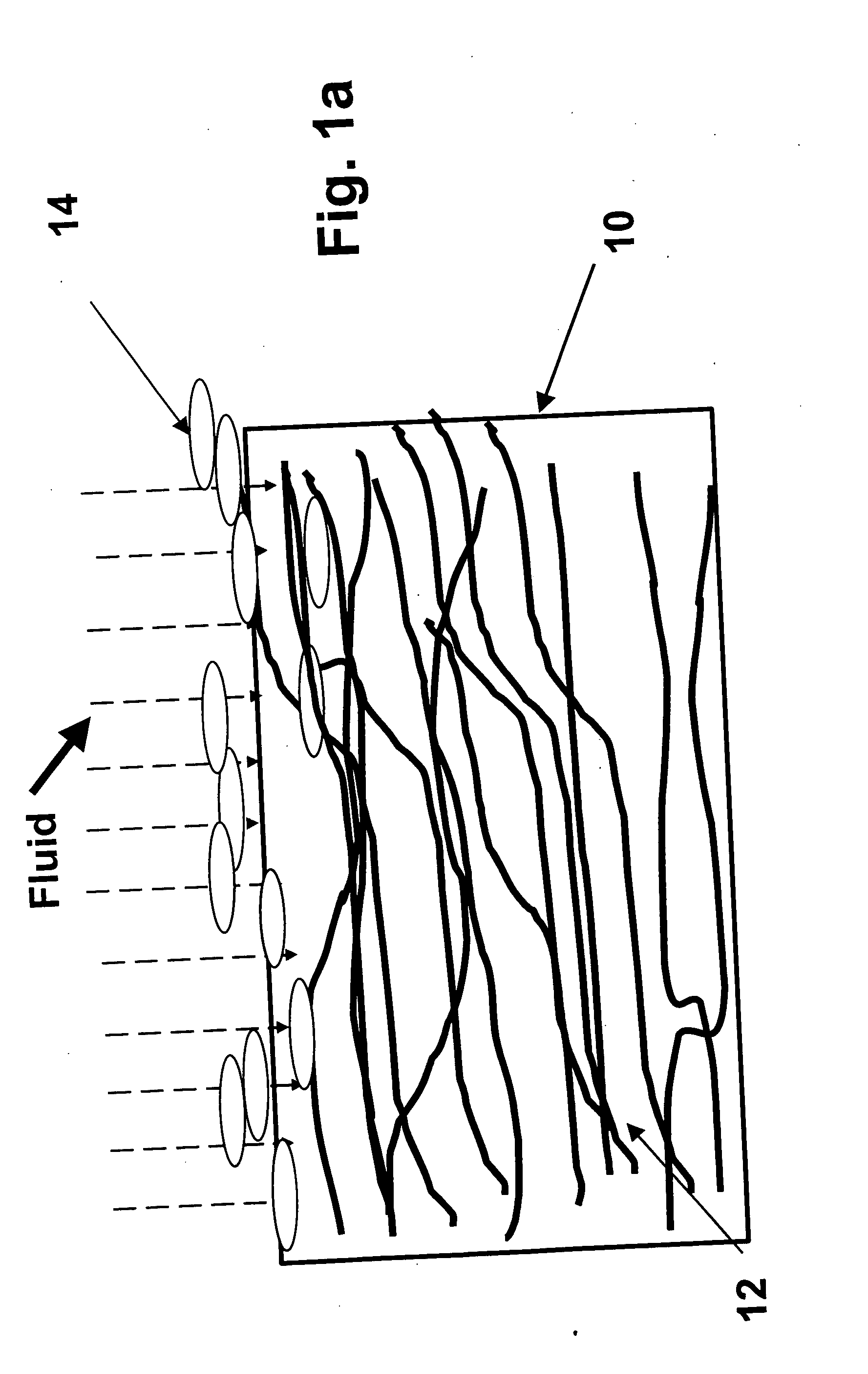
[0119]FIG. 1a is a schematic illustration of a porous woven material having a layer of symmetrical shaped friction modifying material at least partially covering the surface of the porous woven material.

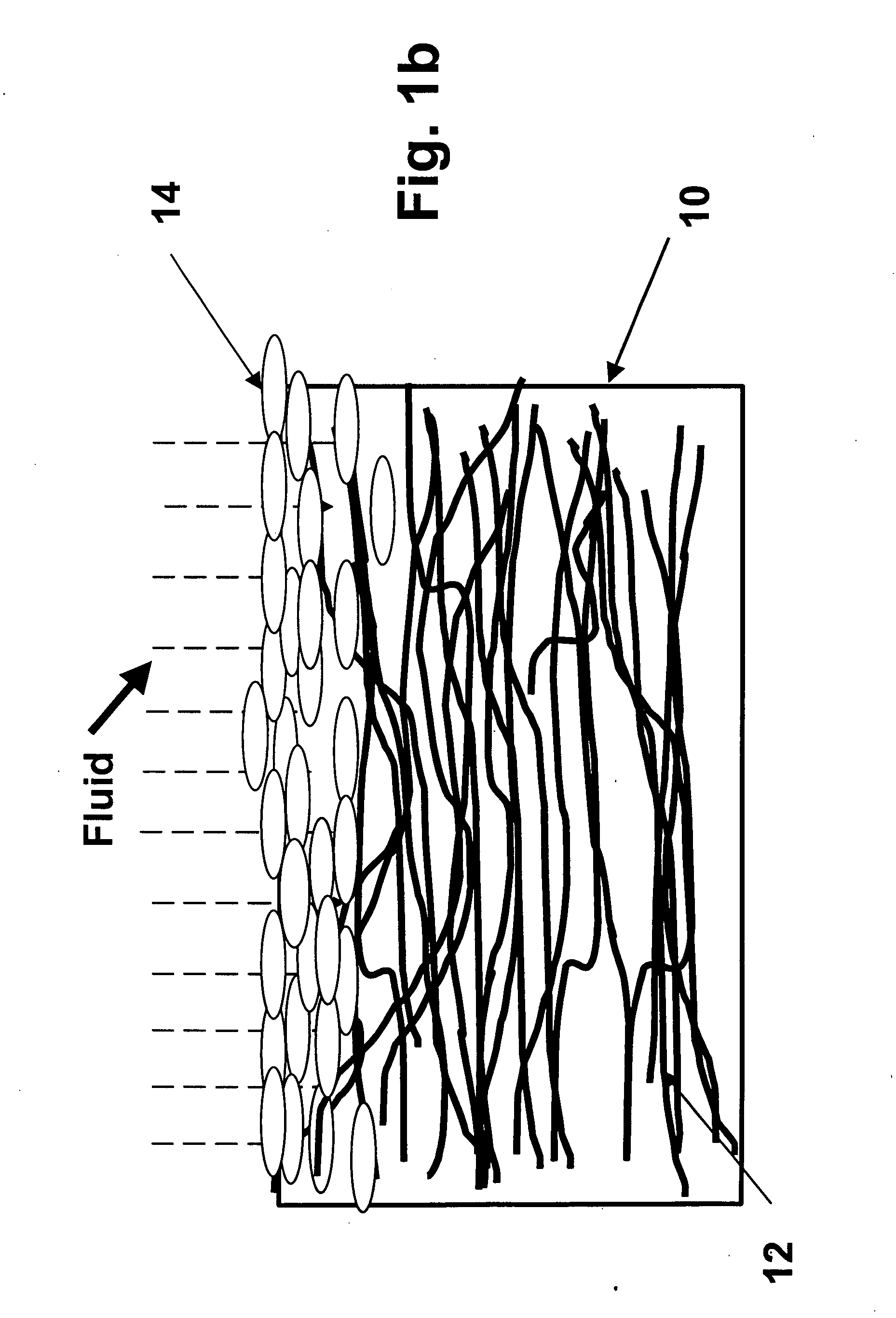
[0120]FIG. 1b is a schematic illustration of a porous woven material having a layer of symmetrical shaped friction modifying material fully covering the surface of the porous woven material.

example ii

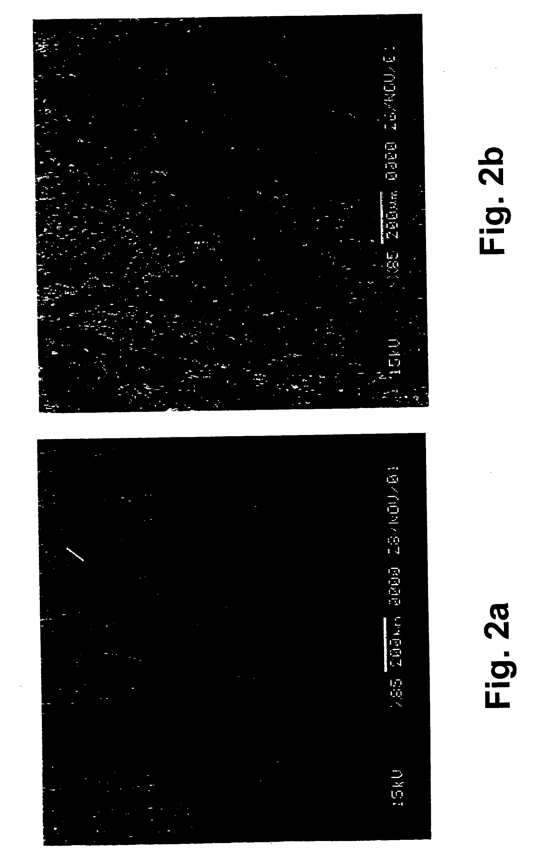
[0121]FIG. 2a is a scanning electron microphotograph showing an uncoated porous woven material.

[0122]FIG. 2b is a scanning electron microphotograph showing a porous woven material partially coated with symmetrically shaped friction modifying particles.

[0123]FIG. 2c is a scanning electron microphotograph showing a porous woven material partially coated with symmetrically shaped friction modifying particles.

[0124]FIG. 2d is a scanning electron microphotograph showing a porous woven material coated with symmetrically shaped friction modifying particles.

[0125] These SEMs show how the some of the friction modifying material penetrates into the warp and weft of the woven material while other of the friction modifying material remains on the surface of the woven material, thus giving the friction material its very desirable anti-shudder characteristics. Also these SEMs also show the high porosity of the friction material.


PUM

PropertyMeasurementUnit
surface smoothnessaaaaaaaaaa
particle sizeaaaaaaaaaa
surface speedsaaaaaaaaaa

Abstract

The present invention relates to a friction material comprising a primary layer material layer and at least a partial coating of symmetrically shaped friction modifying particles on at least one surface of the primary layer for use as an anti-shudder friction material.

Description

TECHNICAL FIELD [0001] The present invention relates to a non-asbestos, non-metallic material comprising a first layer of a base material and a second layer of friction modifying particles that at least partially coat the base material. The friction modifying particles have symmetrical geometric shapes. The invention further relates to a composite friction material comprising the above described coated material impregnated with a suitable resin material. [0002] The friction material of the present invention has improved anti-shudder characteristics, high coefficients of friction, and improved strength, porosity, wear resistance and noise resistance. BACKGROUND ART [0003] New and advanced transmission systems and braking systems are being developed by the automotive industry. These new systems often involve high energy requirements. Therefore, the friction materials technology must be also developed to meet the increasing energy requirements of these advanced systems. [0004] In parti...

Claims


Application Information

Patent Timeline
Patent Type & Authority Applications(United States)
IPC IPC(8): C09K3/14F16D13/62F16D69/02
CPCF16D69/02F16D2200/0069F16D69/026Y10T442/20C09K3/14
Inventor LAM, ROBERT C.DONG, FENGCHEN, YIN-FANGCHAVDAR, BULENT
Owner BORGWARNER INC
Why Eureka
Try Eureka