Long nose manipulatable catheter

a manipulable catheter and long nose technology, applied in balloon catheters, blood vessels, surgery, etc., can solve the problems of inadvertent embolism, embolic coils are subject to the same placement risk, and the target site of the malady is difficult to reach, so as to reduce the degree of flexure, and control the curvature and flexure of the joint region

Inactive Publication Date: 2005-04-07
VASCULAR FX
View PDF24 Cites 45 Cited by
  • Summary
  • Abstract
  • Description
  • Claims
  • Application Information

AI Technical Summary

Benefits of technology

[0016] The manipulatable or flexible joint region is generally located at the distal end of the catheter body and is configured to bend when manipulated by the push / pull wire. The bending portion itself may be varied to extend to where the braid terminates, or it may be extended to the bending portion to encompass a portion of the braid. By varying the length of the flexible joint region, the amount of curvature and flexure of the joint region can be controlled. For instance, a joint region having a relatively shortened length between the distal end of the joint region and the terminal end of the braid may allow for a reduced degree of flexure relative to a neutral position of the catheter. In comparison, a lengthened joint region extending to a more proximally located terminal end may allow for a relatively greater degree of flexure. Accordingly, the degree of flexure may be controlled in part by the length of the flexible joint region. Thus, the flexible region may be flexed up to 90° relative to the longitudinal axis of the catheter assembly and in some cases, the flexible region may be flexed up to 180° relative to the longitudinal axis depending upon the length of the flexible joint region. To further facilitate bending of the catheter, additional members such as coils may be incorporated into the device, for instance in the transitional region, to aid in further controlling the bending of the joint region.

Problems solved by technology

Often the target site of the malady is difficult to reach.
Inadvertent embolism due to an inability to contain the fluid agent within the aneurysm is one risk which might occur when using fluid embolic agents.
Some embolic coils are subject to the same placement risks as that of fluid embolic agents in that it is difficult to contain the occlusive coil within the open space of the aneurysm.
However, none of the above-mentioned devices discloses an intravascular device having a small diameter, highly flexible construction which permits movement along a small-diameter, tortuous vessel path, and having a flexible method of placement to ensure accuracy, as disclosed herein.

Method used


Image

  • Long nose manipulatable catheter
  • Long nose manipulatable catheter
  • Long nose manipulatable catheter

Examples


Embodiment Construction

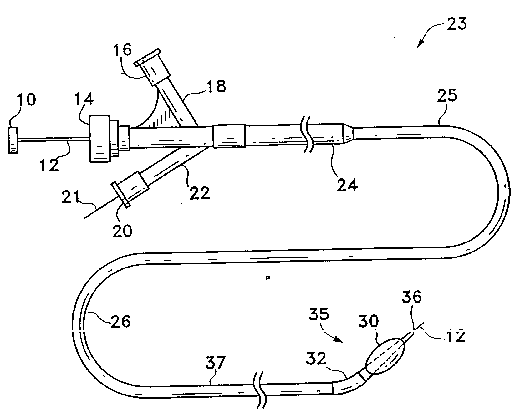
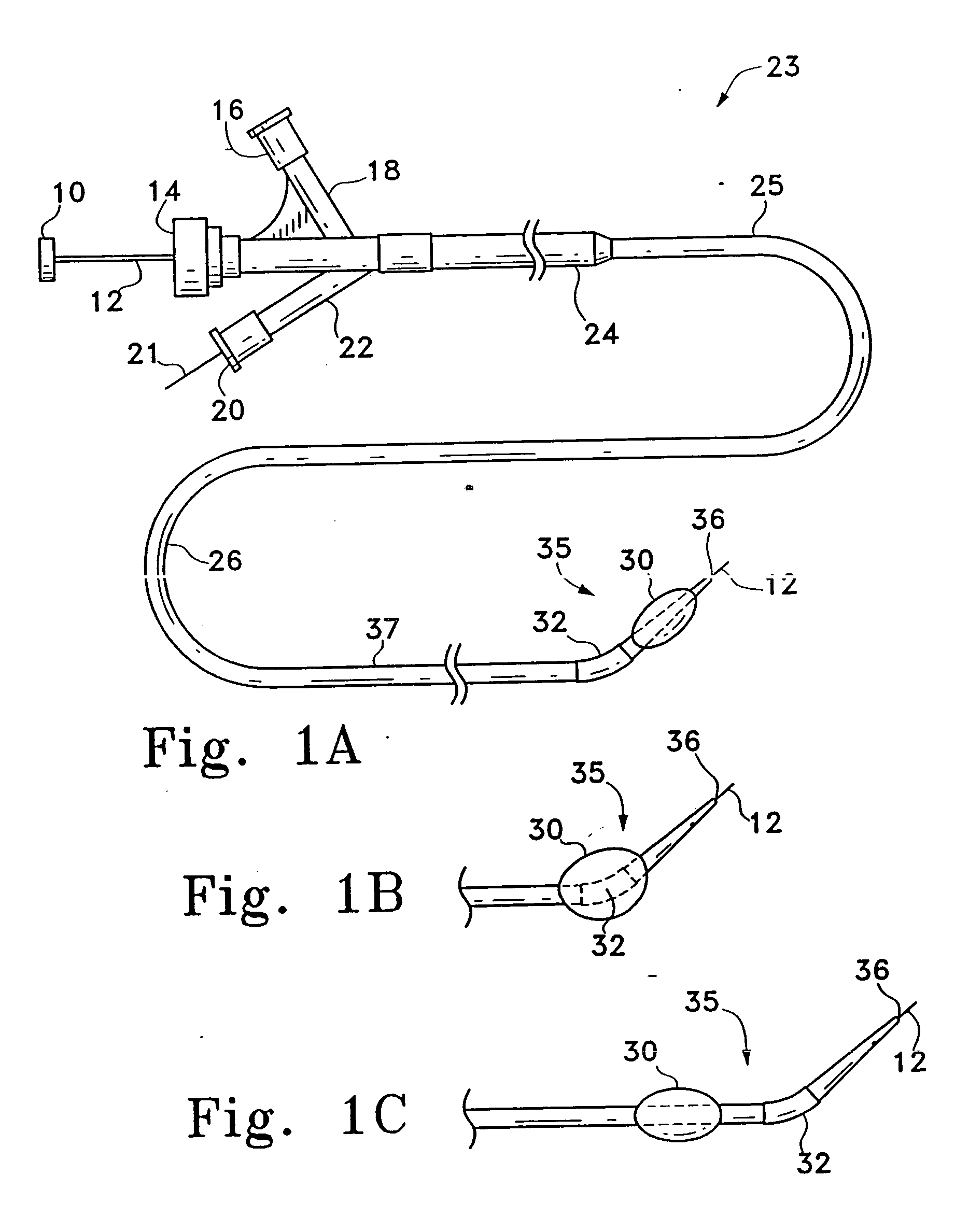
[0037] This invention involves a multi-lumen catheter for the delivery of vaso-occlusive materials or implants. The device may optionally include a balloon member. The device is shown in detail in the figures wherein like numerals indicate like elements. The catheter preferably includes a shapeable, flexible distal section which may be in the vicinity of the balloon, if the balloon member is utilized. The flexible section, or “hinge region”, preferably is manipulated from outside the body during the process of delivering the vaso-occlusive device or material. The terms “hinge region”, “hinge”, or “flexible joint” may be used interchangeably.

[0038]FIG. 1A shows a catheter assembly 23 made according to one variation of the invention. This variation of the catheter assembly 23 includes a catheter shaft 25 composed of a flexible, thin walled body or tube 26 having an inner lumen which extends between proximal and distal catheter ends 24, 37, respectively. The tube 26 is preferably a ge...


PUM


Abstract

A long nose manipulatable catheter is described herein. The catheter generally comprises a flexible joint region defining a main lumen and an adjacent wire lumen. The wire lumen has an opening near or at a distal end of the flexible joint region and a push/pull wire can be pushed or pulled through the wire lumen. The catheter assembly may also comprise at least one radio-opaque marker band for securing the push/pull wire. The joint region has a predetermined length sized to affect a flexure of the joint and is generally located at the distal end of the catheter. The joint region itself may be varied to extend distally from where the braid terminates, or it may extend to encompass a portion of the braid. By varying a length of the joint region, the amount of curvature and flexure of the joint region can be controlled.

Description

FIELD OF THE INVENTION [0001] The invention is generally in the field of intravascular devices. More particularly, it relates to intravascular catheters having a flexible and manipulatable hinge or joint region. The delivery lumen may be also used for placement of occlusive materials, e.g., in an aneurysm. BACKGROUND OF THE INVENTION [0002] Endovascular therapy has been used to treat different conditions, such treatments including control of internal bleeding, occlusion of blood supply to tumors, and occlusion of aneurysm. Often the target site of the malady is difficult to reach. Because of their ability to access remote regions of the human body and deliver diagnostic or therapeutic agents, catheters are increasingly becoming components of endovascular therapies. Generally, catheters are introduced into large arteries, such as those in the groin or in the neck, and then pass through narrowing regions of the arterial system until the catheter's distal tip reaches the selected deliv...

Claims


Application Information

Patent Timeline
Patent Type & Authority Applications(United States)
IPC IPC(8): A61F2/06A61M25/00A61M25/01A61M25/10
CPCA61M25/0068A61M25/008A61M25/0136A61M25/0147A61B17/1214A61M2025/015A61M2025/1079A61M2025/1093A61M25/10A61M25/0141A61M25/0012
Inventor LEVINE, MARC-ALANHEBERT, STEPHEN
Owner VASCULAR FX
Why Eureka
Try Eureka