Storage system

a storage system and storage technology, applied in the field of storage systems, can solve problems such as data corruption and input-output fault, and the concentration of load or fault tolerance decrease, and achieve the effect of reducing the concentration of load or fault toleran

Inactive Publication Date: 2005-04-07
HITACHI LTD
View PDF4 Cites 84 Cited by
  • Summary
  • Abstract
  • Description
  • Claims
  • Application Information

AI Technical Summary

Benefits of technology

[0008] An object of the present invention is to prevent data corruption and an input-output fault during system operation and change the configuration information about a storage virtualization apparatus in a storage system having a virtualization apparatus of redundant configuration.
[0014] According to the present invention, the configuration information of a virtual volume can be changed during system operation by preventing as much influence of an input-output temporary hold as possible. Consequently, data can migrate from one storage device to another storage device during system operation. Moreover, even a virtualization apparatus not having th copy function can shift data. A storage device that can change an allocation destination of the virtual volume can be realized during operation in a redundant configuration.

Problems solved by technology

In such a storage virtualization system, the modification of the configuration information during system operation changes the destination during input-output processing and causes data corruption and an input-output fault.
Accordingly, a method for reducing the storage virtualization apparatuses that operate concurrently during a configuration change to only one apparatus can be considered, but a problem that concentration of a load or fault tolerance decreases is arisen.

Method used


Image

  • Storage system
  • Storage system
  • Storage system

Examples


first embodiment

[0046] First, a first embodiment is described with reference to FIGS. 1 to 8.

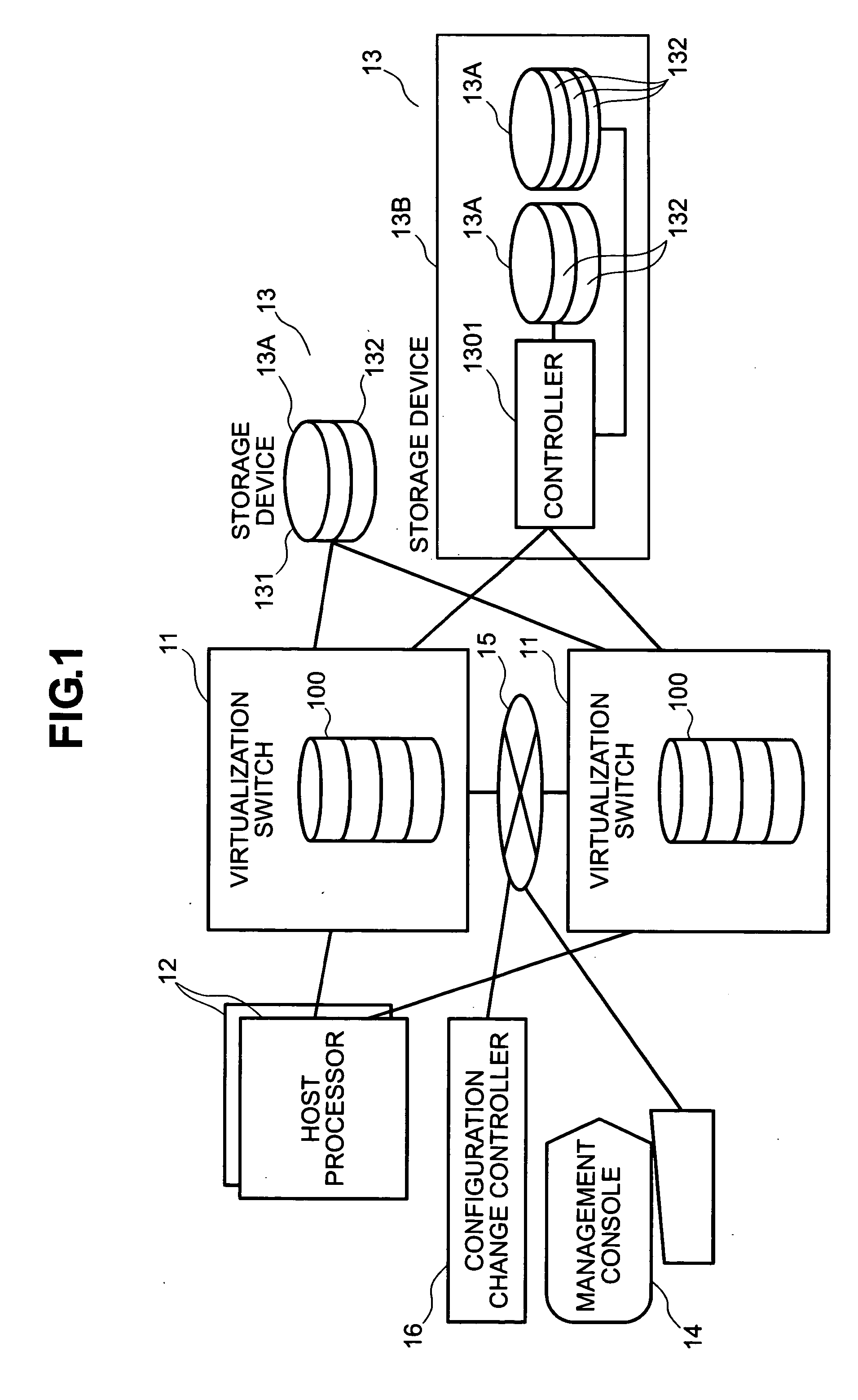
[0047]FIG. 1 is a drawing showing the overall configuration of a storage system.

[0048] The storage system connects at least one host processor 12, a plurality of storage devices 13, a plurality of virtualization switches 11, a configuration change controller 16, and a management console 14 to a network 15 such as a LAN.

[0049] The host processor 12 is a computer that uses data stored in the storage device 13. The host processor 12 may be a file server having a function provided to another computer that does not connect a storage area which the virtualization switch 11 provides to the virtualization switch 11.

[0050] The storage device 13 is provided with a memory unit 13a or a memory unit system 13b. In this case, the memory unit 13a is a single memory unit such as a hard disk drive or a DVD drive. The memory unit system 13b is a storage subsystem having the plural memory units 13a and a controller 1301 th...

second embodiment

[0111] Next, a second embodiment is described with reference to FIGS. 9 to 11.

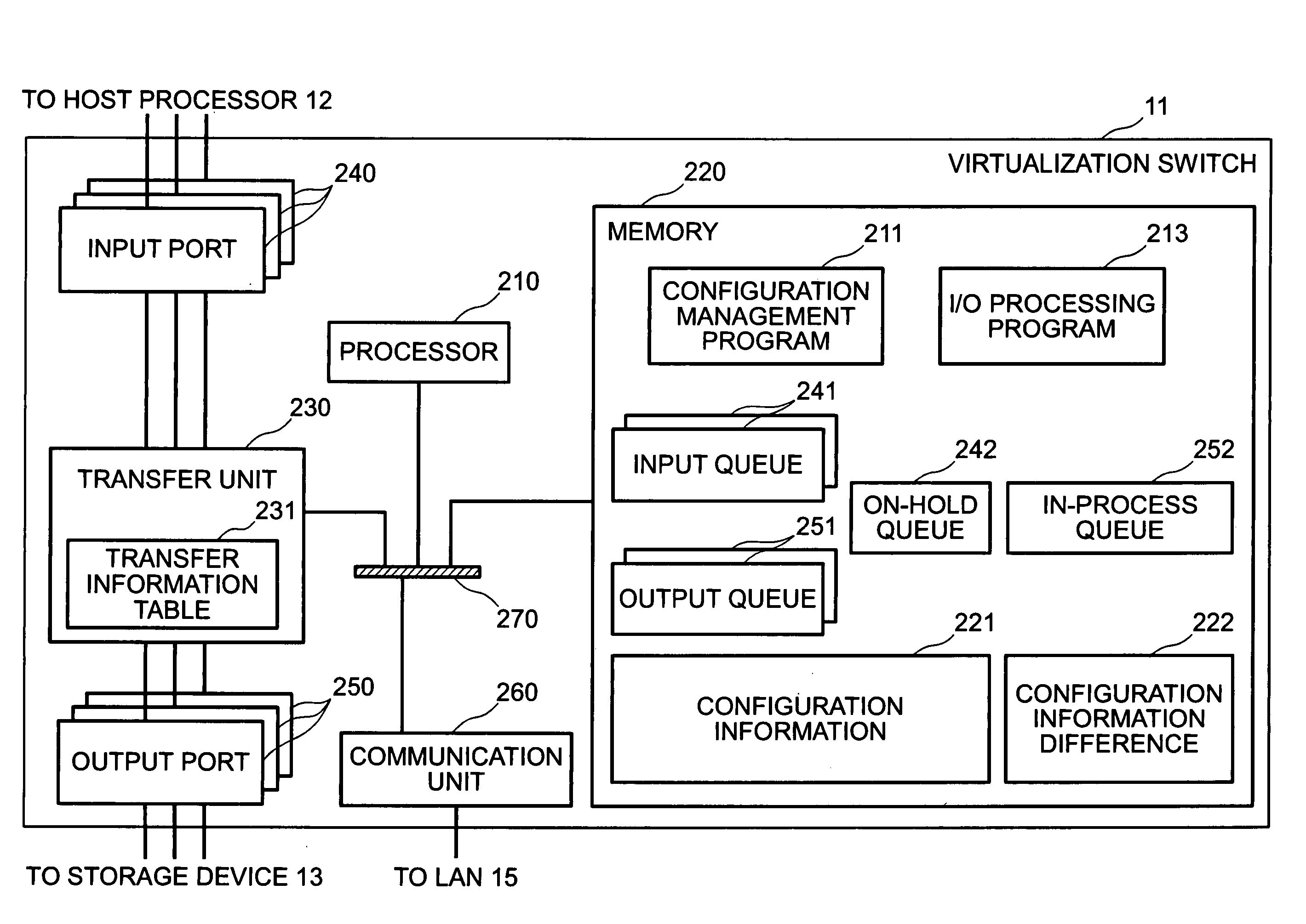
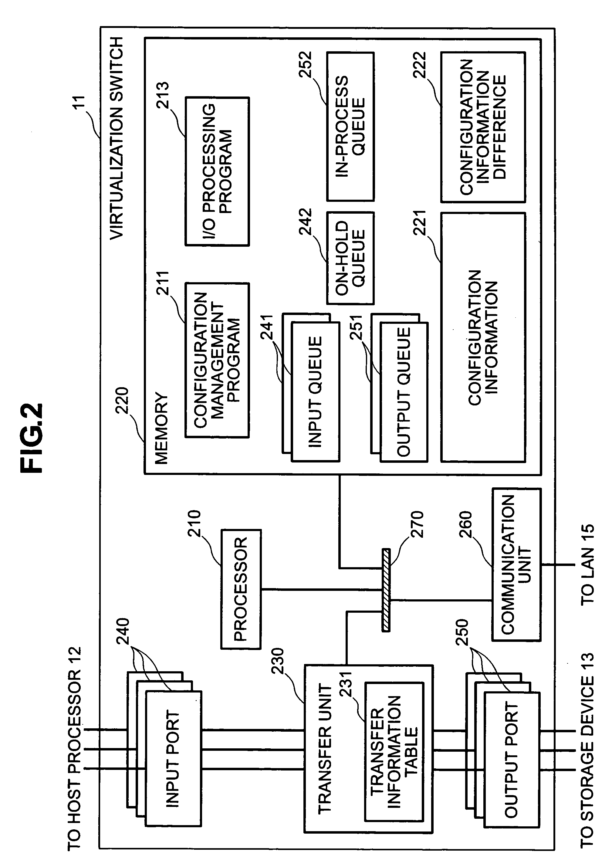
[0112]FIG. 9 shows the internal configuration of the virtualization switch 11 in a storage system.

[0113]FIG. 9 differs from the virtualization switch 11 shown in FIG. 2 in that the processor 161 connected to the bus 270 is provided, the configuration change control program 212 is stored in the memory 220, and the processor 161 executes this configuration change control program 212. In this case, the processor 161 is provided with a timer 165, and the processing of the configuration change control program 212 is activated periodically by this timer 165. The timer 165 may be a timer realized by software.

[0114] According to this embodiment, the virtualization switch 11 can function as the configuration change controller 16 by incorporating the configuration change control program 212 and the processor 161 in the virtualization switch 11 (the virtualization switch 11 that functions in this manner is also her...

third embodiment

[0125] Next, a third embodiment is described with reference to FIGS. 12 to 18.

[0126]FIG. 12 shows the internal configuration of the virtualization switch 11 in a storage system.

[0127] As compared with the virtualization switch 11 shown in FIG. 9, FIG. 12 differs in that a temporary hold control table 223 is provided, the plural in-process queues 252 are provided, and double-buffered configuration information 221a, 221b is provided. The processor is provided with the timer 215.

[0128] The temporary hold control table 223 controls whether the input-output is held temporarily by storing the result of associating each entry of the configuration information 221 with the in-process queue 252. The reason why the plural queues to be processed 252 are provided is to limit a completion wait and input-output held temporarily by dividing the in-process queues 252 according to an input-output destination address. The configuration information 221 has double-buffereds to shorten the processing t...


PUM


Abstract

In a storage system having a plurality of virtualization apparatuses that allocate a storage area which a storage device has, form a plurality of virtual volumes, and process input-output from a host processor to one of the virtual volumes, a request for completing all the input-output being processed that is received from the host processor and temporarily holding the input-output processing received subsequently is issued to the plurality of virtualization apparatuses, when a completion report of the processing of the input-output in response to the request is received from the plurality of virtualization apparatuses and the completion report is received from all the virtualization apparatuses to which the request was issued, an instruction of an allocation change of the storage area of the storage device is sent to all the virtualization apparatuses, and when the completion report of the allocation change is received from all the virtualization apparatuses, the storage area of the storage device is allocated to the virtual volume by sending an instruction for releasing a state of the input-output held temporarily to all the virtualization apparatuses.

Description

BACKGROUND OF THE INVENTION [0001] 1. Field of the Invention [0002] The present invention relates to a storage system, and more particularly to a change in the allocation of a real storage area to a virtual volume in a storage system having a virtualization apparatus of a redundant configuration. [0003] 2. Description of the Prior Arts [0004] In the so-called SAN (Storage Area Network), a system that sets a plurality of virtual volumes with reference to the storage area of a storage device and uses their volumes from a host processor via a network is known. [0005] Regarding a storage virtualization apparatus that virtualizes the storage device connected through the network and enables input-output (I / O) from the host processor, for example, there is such a system as disclosed in Japanese Unexamined Patent Application Publication No. Hei 2000-242434 (Patent Reference 1). According to this art, a storage device to which a virtual storage area provided to a host is allocated is changed...

Claims


Application Information

Patent Timeline
Patent Type & Authority Applications(United States)
IPC IPC(8): G06F3/06
CPCG06F3/0619G06F3/0631G06F3/0635G06F3/0647G06F11/2089G06F3/0665G06F3/067G06F11/004G06F11/1443G06F3/0664
Inventor SERIZAWA, KAZUYOSHISHIMOZONO, NORIOYAMAMOTO, YASUTOMOIWAMI, NAOKO
Owner HITACHI LTD
Why Eureka
Try Eureka