Tool for facilitating the removal and replacement of engine valve stem springs and seals

a technology for engine valve stem springs and tools, which is applied in the field of tools for facilitating the removal and replacement of engine valve stem springs and seals, which can solve the problems of inconvenient and laborious process, inconvenient removal of springs, and injuring mechanics in the process, and the most difficult and dangerous activities in the repair and replacement process of automobile mechanics

Inactive Publication Date: 2005-04-14
ALANIS FRANSISCO
View PDF13 Cites 10 Cited by
  • Summary
  • Abstract
  • Description
  • Claims
  • Application Information

AI Technical Summary

Benefits of technology

[0026] It is a further object of the present invention to provide a tool for the removal and replacement of valve springs on an engine in a manner that allows the mechanic to move from one set of valve springs to the next without time consuming repositioning of the tool on the engine cylinder head.
[0027] In fulfillment of these and other objectives, the present invention provides a tool for the removal and replacement of valve springs on the cylinder head of an internal combustion engine while the cylinder head is either mounted to the engine block within the vehicle or is positioned on a work bench apart from the engine. The tool comprises a bracket component that is mounted by a number of bolts to the cylinder head to be worked on. The bracket includes a number of upright threaded bolts each associated with an adjacent upright guide. A pressure plate is progressively...

Problems solved by technology

Many components on internal combustion engines for automobiles wear out over time and must be replaced.
One of the most difficult and dangerous activities in the repair and replacement process for automotive mechanics is the compression of these strong valve springs in order to carry out their removal and th...

Method used


Image

  • Tool for facilitating the removal and replacement of engine valve stem springs and seals
  • Tool for facilitating the removal and replacement of engine valve stem springs and seals
  • Tool for facilitating the removal and replacement of engine valve stem springs and seals

Examples


Embodiment Construction

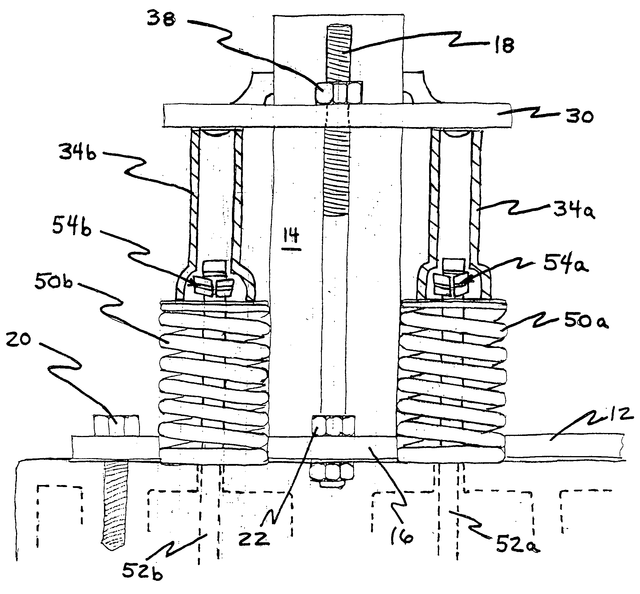
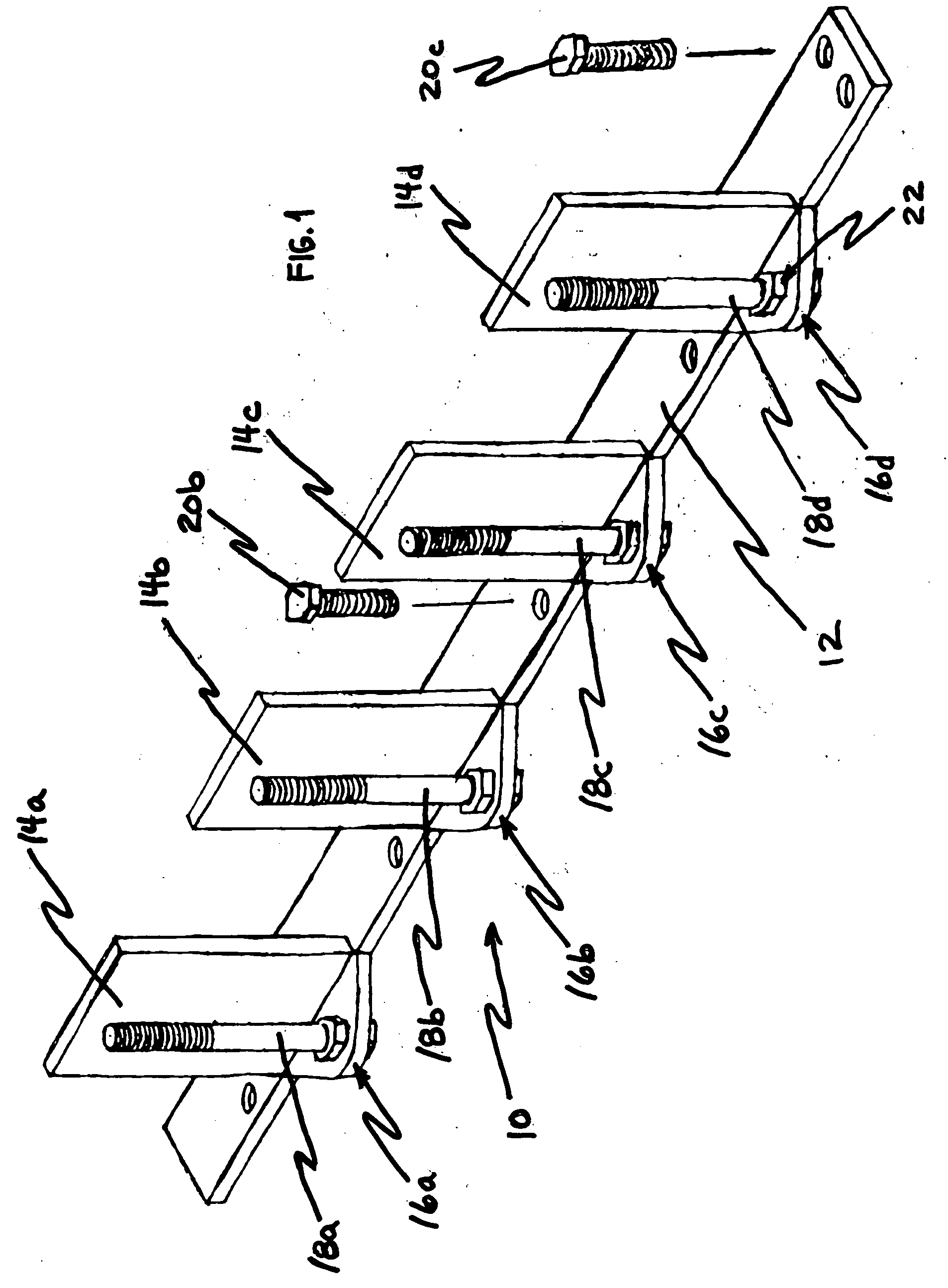
[0031] Reference is made first to FIG. 1 for a description of the primary bracket component of the tool of the present invention. FIG. 1 shows in a perspective view the structure and arrangement of the various parts of bracket member 10. Longitudinal attachment plate 12 of bracket member 10 is bolted to an engine cylinder head (not shown) by means of bolts 20a through 20c. Appropriate apertures are positioned on attachment plate 12 to match with standard cylinder head bolt holes known in the industry. The structure shown in FIG. 1 is that designed for attachment to one cylinder head of a Ford 4.6 liter V-8 engine. Alternative applications would merit modifications to the length of attachment plate 12 and the positioning of the bolt apertures.

[0032] Aligned along one edge of attachment plate 12 and rigidly attached thereto are a plurality of upright bolts 18a through 18d and a plurality of upright guides 14a through 14d. Each upright bolt 18a through 18d is positioned on an extensio...


PUM

PropertyMeasurementUnit
Forceaaaaaaaaaa
Pressureaaaaaaaaaa
Perimeteraaaaaaaaaa

Abstract

A tool for the removal and replacement of valve springs on the cylinder head of an internal combustion engine while the cylinder head is either mounted to the engine block within the vehicle or is positioned on a work bench apart from the engine. The tool comprises a bracket component that is mounted by a number of bolts to the cylinder head to be worked on. The bracket includes a number of upright threaded bolts each associated with an adjacent upright guide. A pressure plate is progressively positioned on each set of the upright bolts and upright guides. Beneath the pressure plate are positioned two (or more) valve guides that engage the outer upper perimeter of two or more valve springs. A nut is threaded on to the upright bolt in a manner that forces the pressure plate and the valve guides downward onto the valve springs. Compression of the springs releases the split rings or collars that hold the valve springs to the valve stems. The end of the valve stems that incorporate the split ring attachment mechanisms are allowed to move upward into the valve guides while the perimeter of the spring is compressed. In this manner the split ring can be removed and the springs released upon removal of the nut from the threaded upright bolt. The pressure plate may then be moved to the next upright bolt on the bracket to effect removal of the adjacent set of valve springs.

Description

BACKGROUND OF THE INVENTION [0001] 1. Field of the Invention [0002] The present invention relates generally to automotive engines and tools for the repair and replacement of engines and engine parts. The present invention relates more specifically to a tool that facilitates the removal and replacement of valve springs on an internal combustion engine as may be required for the replacement of valve seals on the engine. [0003] 2. Description of the Related Art [0004] Many components on internal combustion engines for automobiles wear out over time and must be replaced. Among these components are the valve seals positioned on the engine cylinder heads. The typical cylinder valve component comprises an elongated shaft or stem with a valve head that rests in a valve seat or seal thereby closing an intake or exhaust port from the cylinder. The typical valve structure includes a strong spring that maintains the valve head tightly against the seat or seal unless a rotating cam forces the sh...

Claims


Application Information

Patent Timeline
IPC IPC(8): B25B27/24B25B27/26
CPCB25B27/24Y10T29/5357Y10T29/53565B25B27/26
Inventor ALANIS, FRANSISCO
Owner ALANIS FRANSISCO
Why Eureka
Try Eureka