Method and apparatus for removing boiling liquid from a tank

Inactive Publication Date: 2005-04-14
LINDE AG
View PDF7 Cites 1 Cited by
  • Summary
  • Abstract
  • Description
  • Claims
  • Application Information

AI Technical Summary

Benefits of technology

[0010] The mass flow through nozzles, screens, valves, etc. reduced during the relaxation vaporization is to be increased by using a supercooled liquid. A relaxation vaporization in an outflow opening is to be prevented as completely as possible. Known systems also aim at providing a supercooled liquid, but do not prevent the occurrence of a relaxation vaporization to the extent desired here.
[0011] According to certain preferred embodiments of the invention, the boiling liquid is relaxed in a receptacle, if possible, to atmospheric pressure. Subsequently, the intermediate receptacle is pressurized. This pressurization takes place by the flowing-in of the same medium as the medium present in the intermediate receptacle and is removed from the same s

Problems solved by technology

Known systems also aim at providing a supercooled liquid, but do not preve

Method used


Image

  • Method and apparatus for removing boiling liquid from a tank
  • Method and apparatus for removing boiling liquid from a tank

Examples


Example

DETAILED DESCRIPTION OF THE DRAWINGS

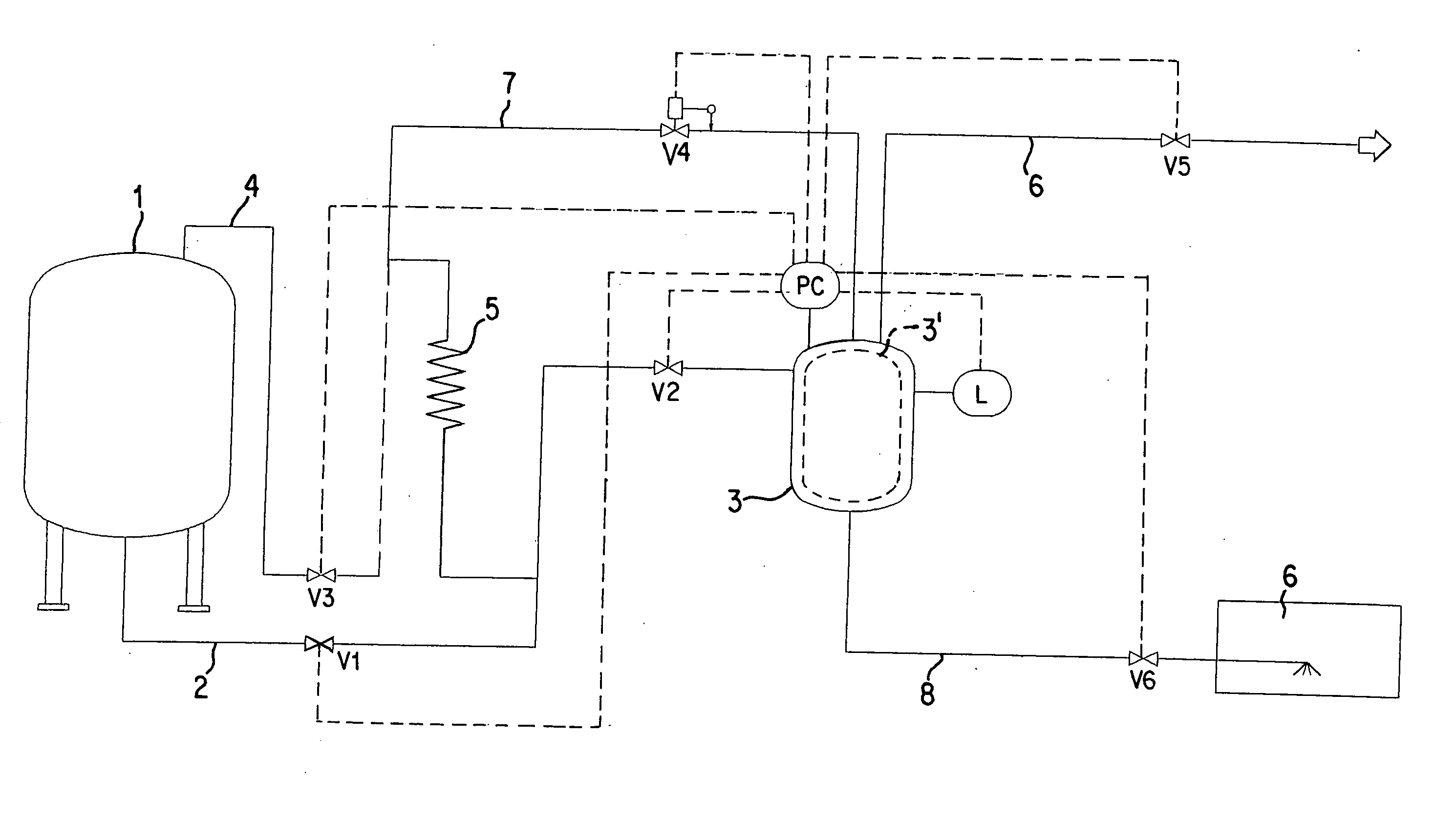
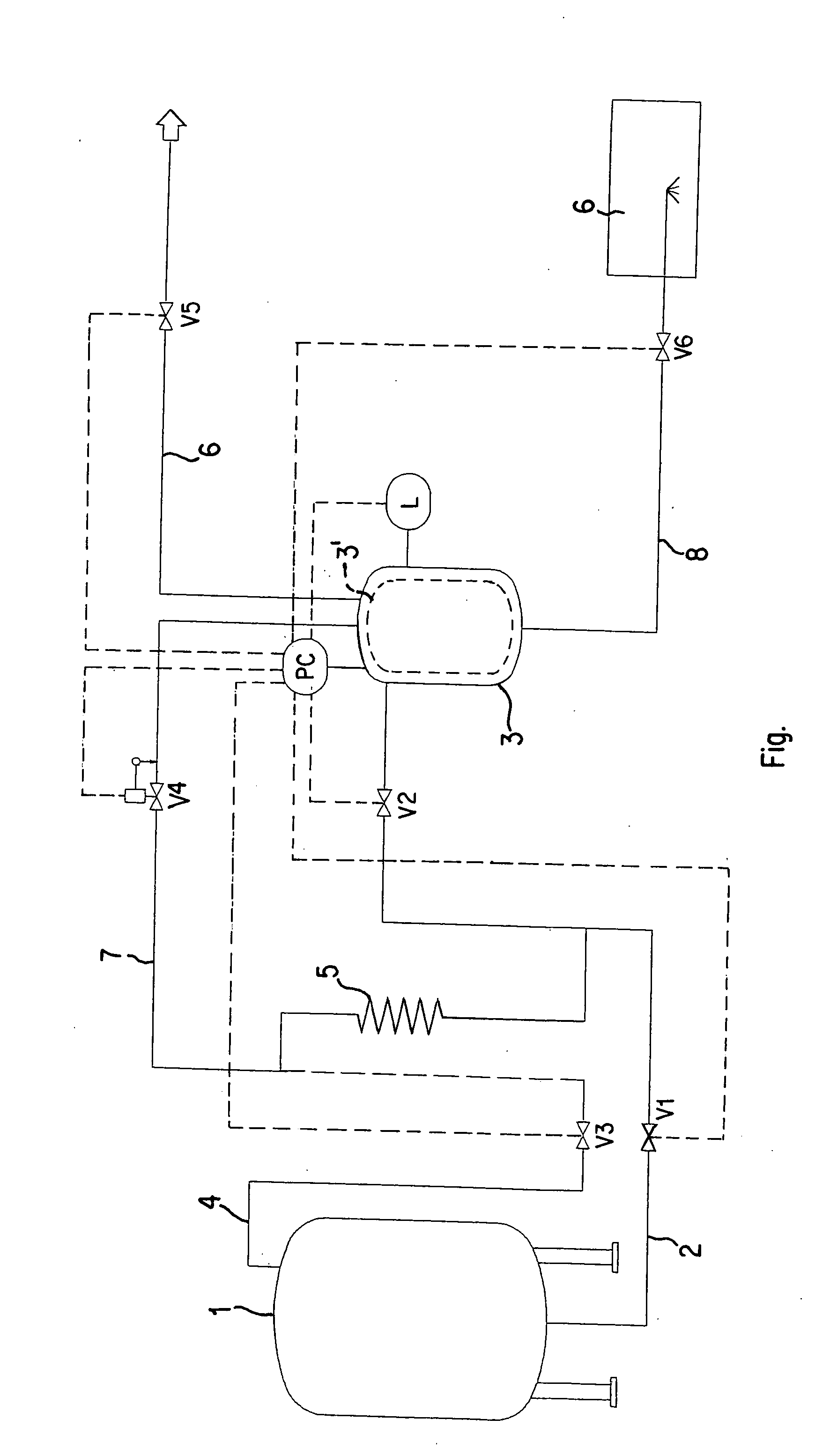
[0016] In a storage tank 1, the liquefied gas is stored at a pressure higher than the ambient pressure in the pertaining phase equilibrium. Liquid flows from the lower part of the tank 1 through tank pipe 2 into the intermediate receptacle 3 and fills the latter to a defined level. The flow from tank pipe 2 is then closed by closing valve V2. The gas is then released from the gas space of the intermediate receptacle 3 by opening valve V5 in pipe 6, and the pressure in the intermediate receptacle 3 is thereby lowered. The fluid in the intermediate receptacle 3 cools in this gas release process. A subsequent pressurization changes the fluid in the intermediate receptacle thermodynamically to a condition of a supercooled liquid.

[0017] The subsequent pressure increase in the intermediate receptacle 3 can take place directly by means of gas from the storage tank 1 or by means of liquid from the storage tank 1, which then becomes gaseous in a vaporize...


PUM


Abstract

A method and apparatus are provided for removing a boiling liquid from a tank. The liquid is removed from the tank and, before the delivery to a consuming device is supplied to an intermediate receptacle in which the boiling liquid is subjected to a pressure reduction and subsequently to a pressure increase.

Description

BACKGROUND AND SUMMARY OF THE INVENTION [0001] This application claims the priority of German Application No. 103 47 129.4 filed Oct. 10, 2003 and German Application No. 10 2004 006346.8 filed Feb. 12, 2004, the disclosures of which are expressly incorporated by reference herein. [0002] The invention relates to a method of removing a boiling liquid from a tank. For removing boiling liquids (for example, liquefied gases) from a tank, normally the present tank pressure is used for generating a flow through nozzles or valves. Only rarely is the boiling liquid fed to a booster pump for generating a condition in which the liquid is supercooled. It is also known that the boiling liquid in an intermediate receptacle is acted upon by a higher pressure in order to produce a supercooled liquid in this manner. In some applications, a partial relaxation of the liquid takes place in an intermediate receptacle behind the tank. The liquid will then flow at a reduced pressure but not supercooled al...

Claims


Application Information

Patent Timeline
IPC IPC(8): F17C1/00F17C7/04F17C9/02
CPCF17C7/04F17C2205/0323F17C2223/0153F17C2223/033F17C2223/046F17C2225/0123F17C2270/07F17C2227/0107F17C2227/0302F17C2227/0393F17C2250/032F17C2250/0626F17C2225/036
Inventor BERGHOFF, RUDOLF ERWIN
Owner LINDE AG
Why Eureka
Try Eureka