Fogging nozzle assembly couplable to a typical handheld blower

Pending Publication Date: 2022-05-05
DJB SOLUTIONS LLC
View PDF0 Cites 0 Cited by
  • Summary
  • Abstract
  • Description
  • Claims
  • Application Information

AI Technical Summary

Benefits of technology

The patent describes an apparatus for fogging a liquid using a blower and a metered core. The apparatus includes a housing with an air inlet and a fogging outlet. The housing has a first end and a second end. A metered core is positioned within the housing and includes a first plurality of radial angled fins to create a low-pressure zone. The low-pressure zone draws the fogging liquid from the liquid container and mixes it with air from the blower. The air vortex core, which is positioned between the metered core and the fogging outlet, includes a second plurality of radial angled fins to guide the fog out of the housing. The apparatus also includes a check valve to equalize the air pressure inside the liquid container with the atmospheric pressure as the fogging liquid is dispensed. The technical effects of the apparatus include efficient fogging with a reduced amount of fogging liquid, improved mixing of the fogging liquid with air, and increased control over the fog output.

Problems solved by technology

In case of a part failure, motors and replacement parts can be hard to find for typical low-cost foggers, and are costly to repair.
The performance of these typical low-cost foggers, in terms of disbursed liquid droplet size, distance traveled of output fog, rate of liquid consumption, and application and tank size, is limited to specifications as established at a time of manufacture.
Typical foggers also have limited range of operation, in that they are unable to achieve consistent fogging while the output is positioned vertically upwards or downward.
They also can be prone to unwanted leaking resulting in liquid chemical product loss.
These typical foggers can produce significant pressure and throw of air molecules; however, these products are not configured to dispense or interact with their stored liquids.

Method used


Image

  • Fogging nozzle assembly couplable to a typical handheld blower
  • Fogging nozzle assembly couplable to a typical handheld blower
  • Fogging nozzle assembly couplable to a typical handheld blower

Examples


Embodiment Construction

[0035]While this disclosure is susceptible of configuration in many different forms, there is shown in the drawings and described herein in detail a specific configuration(s) with the understanding that the present disclosure is to be considered as an exemplification and is not intended to be limited to the configuration(s) illustrated.

[0036]It will be understood that like or analogous elements and / or components, referred to herein, may be identified throughout the drawings by like reference characters. In addition, it will be understood that the drawings are merely schematic representations of the invention, and some of the components may have been distorted from actual scale for purposes of pictorial clarity.

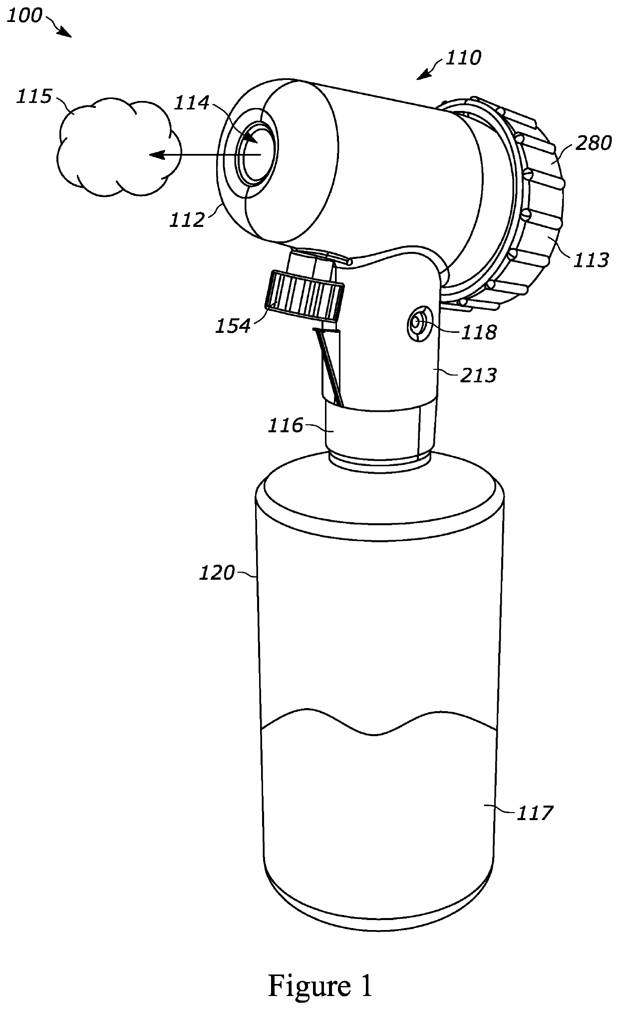
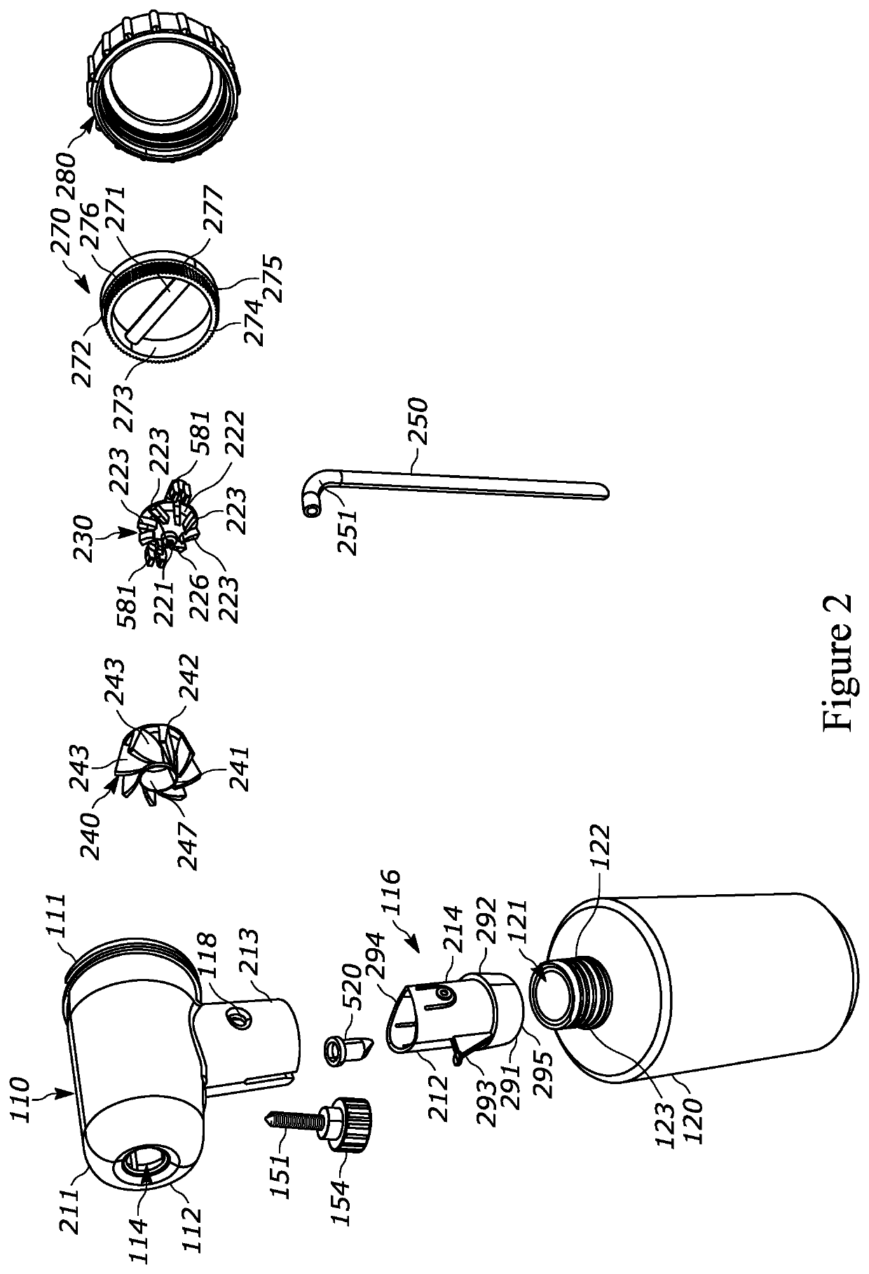
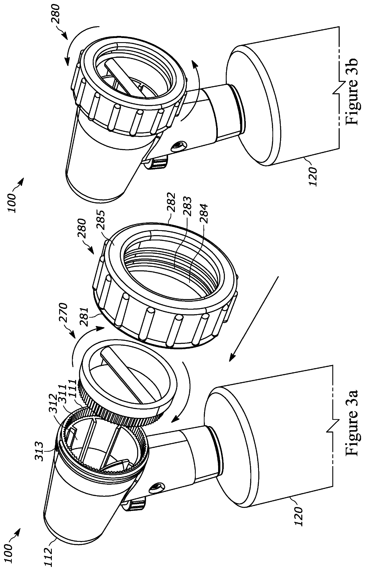
[0037]In accordance with configuration(s) disclosed herein, a nozzle assembly is disclosed that converts one or more existing external air blower products into a fogger, such as an Ultra-Low Volume (ULV) fogger. In at least one configuration the nozzle assembly also allows a u...


PUM


Abstract

A method and apparatus include a housing, a metered core, and an air vortex core. The housing includes a first end and a second end. The housing includes an air inlet opening at the first end to receive air from a blower distinct from the apparatus and a fogging outlet opening to output a fog at the second end. The housing couples to a liquid container that stores a fogging liquid and to the blower. The metered core, disposed within the housing, includes a first plurality of radial angled fins to create a low-pressure zone within the housing which draws the fogging liquid from the liquid container into the housing. The air vortex core, disposed between the metered core and the fogging outlet opening, includes a second plurality of radial angled fins to mix the fogging liquid with the air and guide the fog exiting the housing at the fogging outlet opening.

Description

CROSS-REFERENCE TO RELATED APPLICATION[0001]This application claims priority from U.S. Provisional Patent Application Ser. No. 63 / 109,297 filed on Nov. 3, 2020, entitled “FOGGING NOZZLE ASSEMBLY COUPLABLE TO A TYPICAL HANDHELD BLOWER”, the entire disclosure of which is hereby incorporated by reference in its entirety.BACKGROUND OF THE DISCLOSURE1. Field of the Disclosure[0002]The disclosure relates in general to a nozzle assembly, and more particularly, to a fogging nozzle assembly couplable to a typical handheld blower.2. Background Art[0003]Multiple industries require the application of liquid based chemicals through means of fogging, such as Ultra Low Volume (ULV) fogging, to dispense chemicals, without alteration to their composition. Typical low-cost foggers, self-contained units with internal motor assemblies are powered via alternating current, batteries, or fuel, are able to perform such fogging.[0004]In case of a part failure, motors and replacement parts can be hard to fin...

Claims


Application Information

Patent Timeline
IPC IPC(8): B05B7/04B05B7/00B05B7/10
CPCB05B7/0441B05B7/10B05B7/0081B05B14/00B05B7/2416B05B7/12B05D1/02
Inventor ABRAHAM, BRET J.ABRAHAM, JAMES M.HATCH, ALEX JAMES
Owner DJB SOLUTIONS LLC
Why Eureka
Try Eureka