Device for drying at least one optical glass

Inactive Publication Date: 2015-05-21
SCL INT SPECIAL COATING LAB
View PDF3 Cites 0 Cited by
  • Summary
  • Abstract
  • Description
  • Claims
  • Application Information

AI Technical Summary

Benefits of technology

The patent describes a method for drying optical glass to prevent defects. The drying is done in a way that ensures evenness on both sides of the glass. This method allows for quick and uniform drying of the glass. Additionally, the patent mentions the use of holes at the outlet of each diffuser that help create a consistent flow. Overall, this patent provides a solution for ensuring high-quality optical glass.

Problems solved by technology

However, obtaining a uniform heating temperature throughout the entire surface of the optical glass is not evident with a device having an infrared ray emitter.
During the drying carried out after the application of the first layer of varnish, there may be areas where the varnish is not fully pre-polymerized.
Surface irregularities are likely to appear on the glass, which may extend to cracking of the varnish.
As a consequence, if one of these defects appear, the glass has severely degraded optical properties.

Method used


Image

  • Device for drying at least one optical glass
  • Device for drying at least one optical glass
  • Device for drying at least one optical glass

Examples


Embodiment Construction

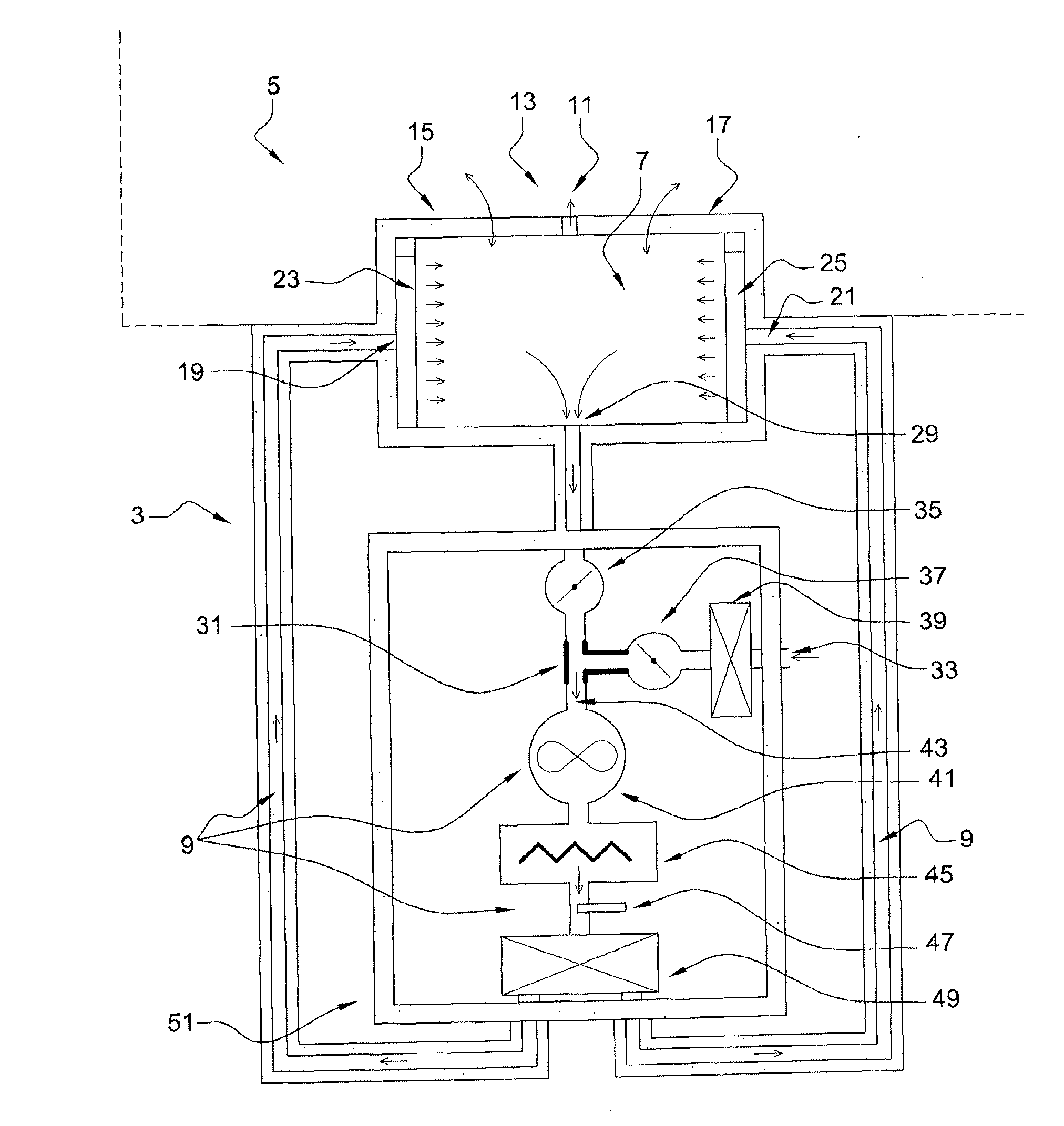
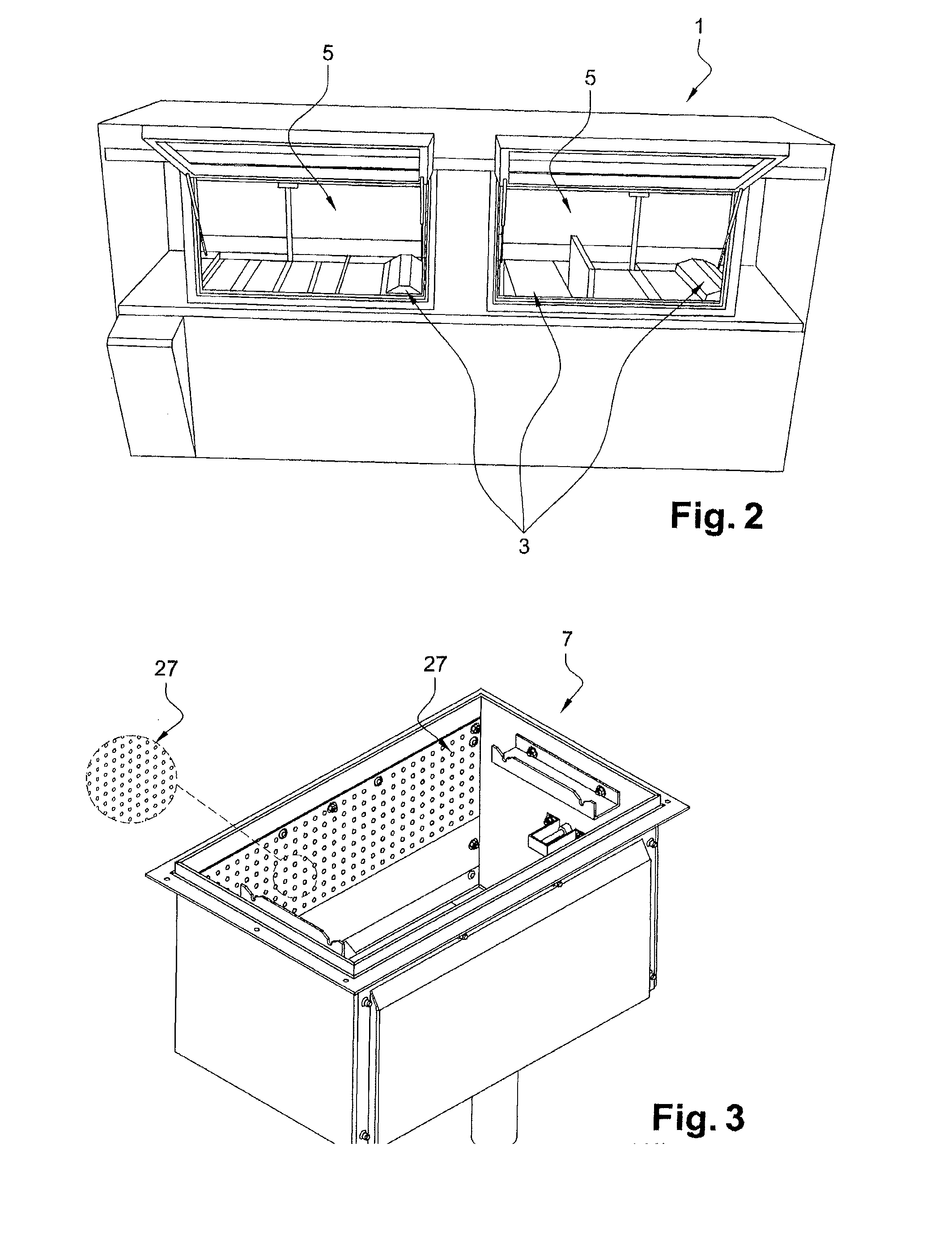
[0043]According to an embodiment described in FIG. 2, a surface treatment bench 1 includes a drying device 3 and an extraction area 5.

[0044]As shown more particularly in FIG. 1, the drying device 3 comprises an enclosure 7 and an air circulation circuit 9.

[0045]According to an embodiment described in FIG. 1, an exhaust port 11 connects the enclosure 7 to the extraction area 5 in fluid communication. An opening system 13 between the enclosure 7 and the extraction area 5 includes two raisable flaps 15 and 17. The gap between the two raisable flaps 15 and 17 constitutes the exhaust port 11.

[0046]The air circulation circuit 9 is connected in fluid communication with two air inlets 19 and 21 to the enclosure 7. Each air inlet 19 and 21 has a diffuser 23 and 25 respectively. According to an embodiment, the diffusers have a planar outlet with a plurality of holes 27 as shown more particularly in FIG. 3. The distance separating the centers of two adjacent holes is between one time and three...


PUM


Abstract

The invention relates to a device (3) for drying at least one optical glass, comprising: a chamber (7), intended to house at least one optical glass, having at least one air inlet (19) arid at least one air outlet (29); a circuit (9) for circulating air, arranged to blow a flow of drying air from said at least one inlet (19) to said at least one outlet (29), the drying device has: an evacuation orifice (11), in fluid communication with the chamber (7), in order to evacuate a first portion of the flow of drying air, called the evacuated airflow, out of the drying device (3); and a manifold collecting: an inflow of a second portion of the flow of drying air, called recovered air, in fluid communication with the chamber (7), from said at least one air outlet (29); an inflow of a flow (33) of air from outside the drying device (3); and having an outlet (29) in fluid communication with the circulating circuit (9).

Description

TECHNICAL FIELD[0001]The present invention relates to a device for drying optical glass.BACKGROUND[0002]It is known to use a drying device composed of an enclosure intended to receive the optical glass or glasses. According to the state of the art, a heating element emitting infrared rays causes a temperature increase in the enclosure. The high temperature in the enclosure drives the drying process. According to the state of the art, the minimum heating temperature has to be over 80° C.[0003]The surface treatment of an optical glass is conducted in several steps. The optical glass undergoes several dryings during the process of surface treatment, particularly after the washing, after application of a first layer of varnish and after application of a possible second layer of varnish.[0004]During the drying carried out after the washing, the increase in temperature allows degassing of the optical glass. The dryings carried out after the application of a first layer of varnish and afte...

Claims


Application Information

Patent Timeline
IPC IPC(8): F26B21/00F26B23/06F26B25/06
CPCF26B21/004F26B23/06F26B25/06F26B9/06F26B21/04F26B3/06Y02E60/10
Inventor GEHRIG, JEANGEHRIG, DENIS
Owner SCL INT SPECIAL COATING LAB
Why Eureka
Try Eureka