Pliers for crimping work pieces

a technology for crimping work pieces and pliers, which is applied in the direction of pliers, metal-working hand tools, manufacturing tools, etc., can solve the problems of the relative position of the two portions of the movable handle being buckled in a somewhat awkward way, and achieve the effect of easy production by punching

Active Publication Date: 2005-04-14
WEZAG GMBH & CO KG
View PDF9 Cites 6 Cited by
  • Summary
  • Abstract
  • Description
  • Claims
  • Application Information

AI Technical Summary

Benefits of technology

[0009] The tooth segment of the locking mechanism as well as the stops of the stop mechanism preferably extends over the entire thickness of the first portion of the handle facing the movable pivot jaw. In this way, they may be easily produced by punching without losing required stability. The plate-shaped punching element of the first portion of the handle may be designed as one piece or also to include two pieces, respectively. Preferably, the arrangement is chosen to be symmetric with respect to the plane of main extension of the pliers, meaning also in the center of the thickness of the pliers. Two pressure levers may then be arranged symmetrically within the thickness of the pliers as seen from the inside towards the outside. These pressure levers may also be designed as punching elements. Preferably, they are located in the same plane as the pivot jaws and as the part of the pivot jaws facing the first portion of the handle, respectively. In case the crimping dies located in the

Problems solved by technology

However, this relative position of the two portions of the movable handle is buckled in a somewhat awkward way.
This is sometimes found to be disturbing

Method used


Image

  • Pliers for crimping work pieces
  • Pliers for crimping work pieces
  • Pliers for crimping work pieces

Examples


Embodiment Construction

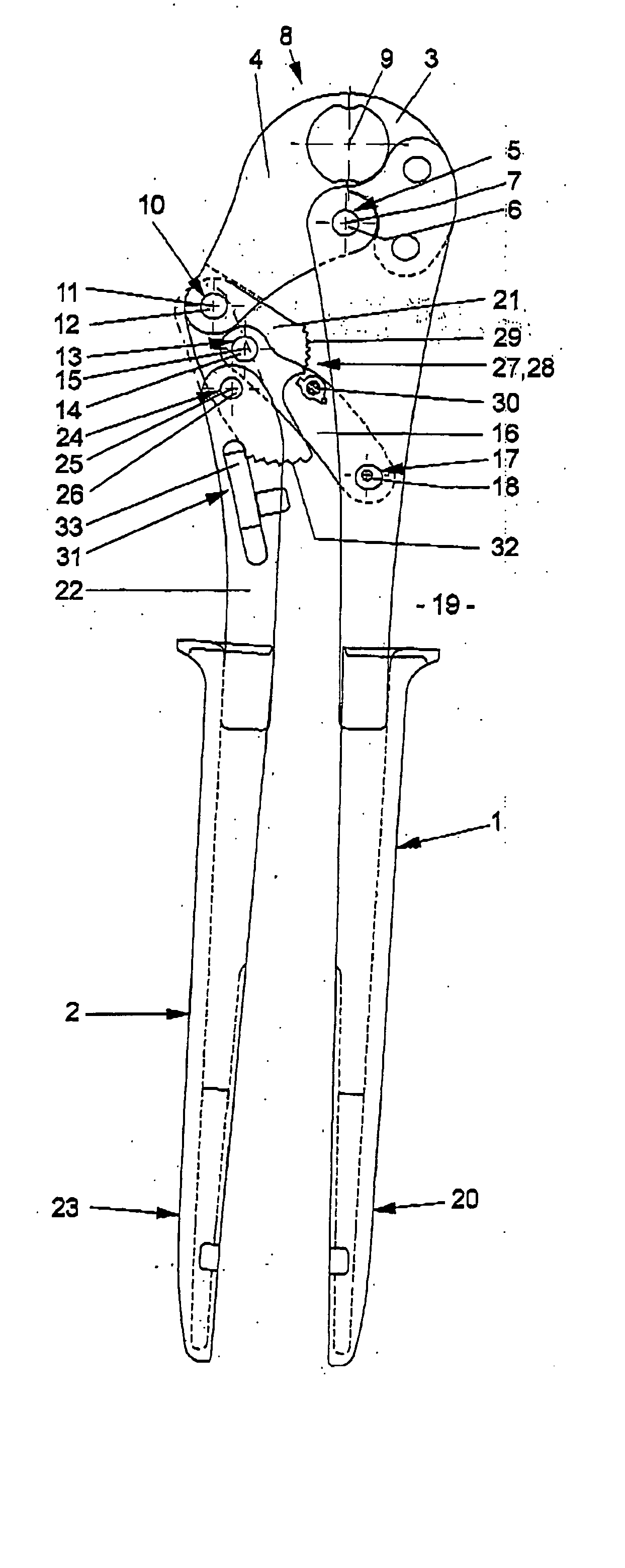
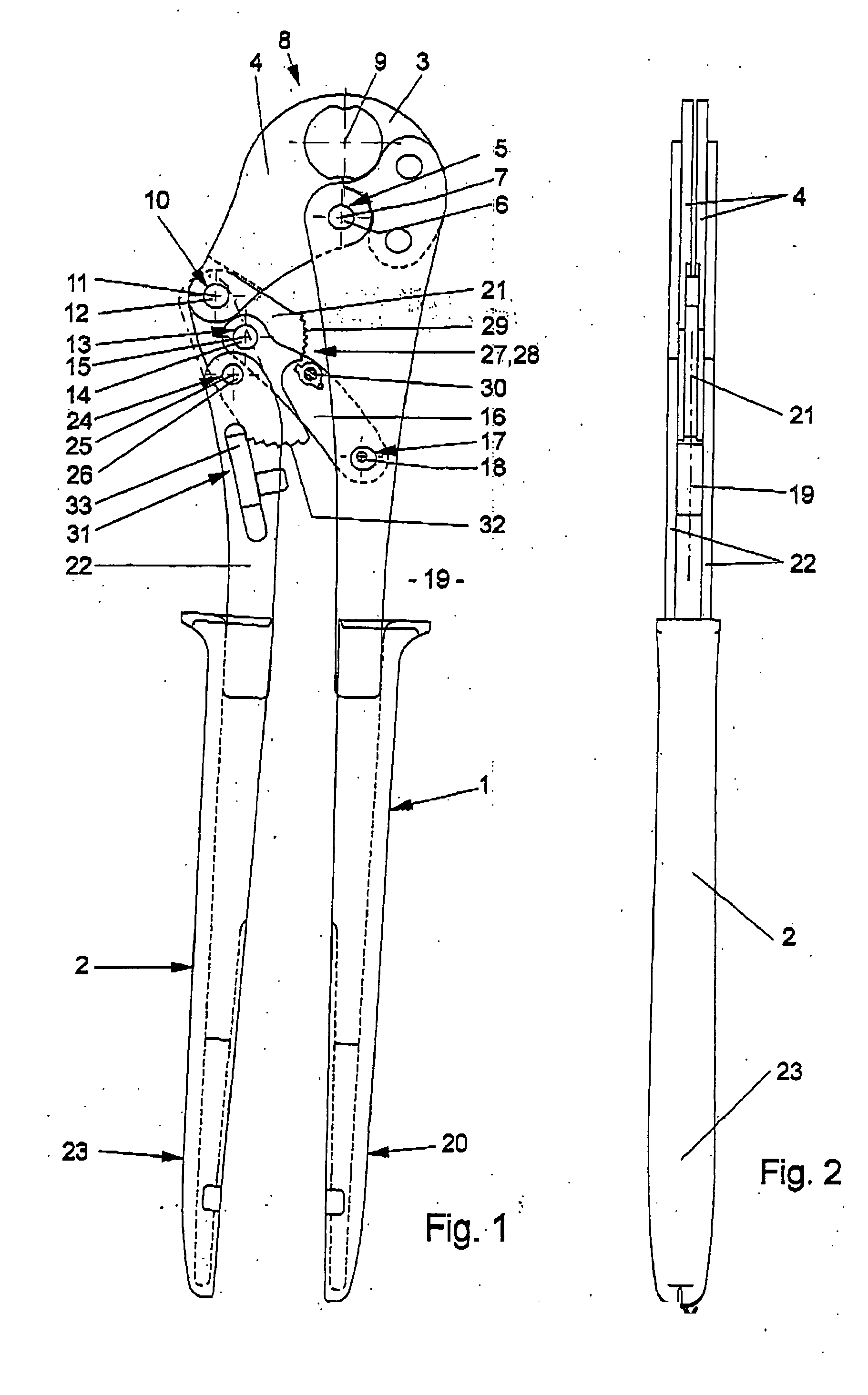
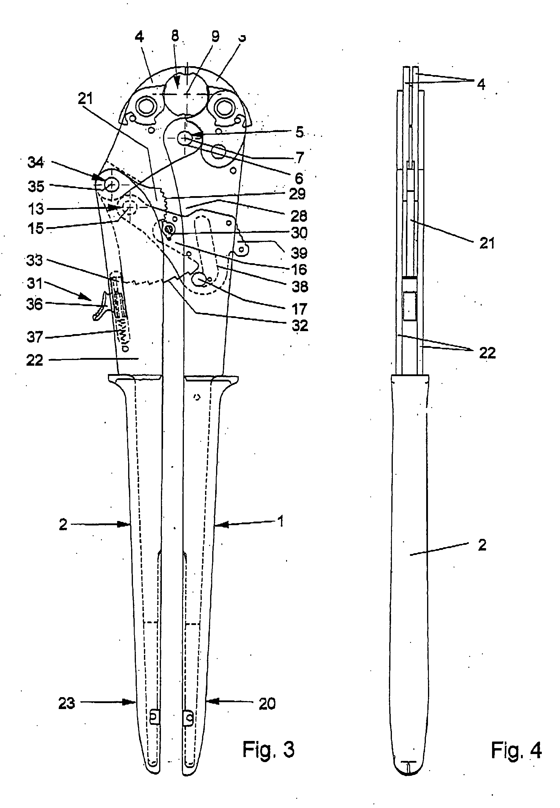
[0026] Referring now in greater detail to the drawings, FIG. 1 illustrates a first exemplary embodiment of the novel pliers including handles 1 and 2. The handle 1 is fixedly connected to a pivot jaw 3 to be commonly rotated and such that these two elements form a stationary portion of the pliers. The pivot jaw 3 and the handle 1 may also be designed as one piece. The handle 1 is also referred to as stationary handle, although, for an activation of the pliers, it is only important that there is a relative movement of the handles 1 and 2 with respect to one another. In addition to the stationary pivot jaw 3, there is a movable pivot jaw 4 being pivotally connected to the stationary portion of the pliers 1, 3 by a joint 5. The stationary handle 1 may be designed as a semi shell or to have a plate design such that its legs or plates extend approximately symmetrically to the plane of main extension 19 of the pliers. The same applies to the movable handle 2. A pin 6 extends through the l...


PUM


Abstract

Pliers for crimping work pieces include a pliers head, a first pivot jaw (4) and a second pivot jaw (3). A common joint (5) pivotally connects the first and second pivot jaw (4, 3). Two dies together form a crimping die (8). A first handle (2) is connected to the first pivot jaw (4). The first handle (2) is divided into at least a first portion (21) and a second portion (22). The first portion (21) is designed as a plate. A second handle (1) is connected to the second pivot jaw (3). The first handle (2) and the second handle (1) are movable with respect to one another and operable to crimp the work piece in a few crimping steps. A locking mechanism (28) includes a tooth segment (29), and it serves to attain a defined closed position of the dies. The tooth segment (29) is designed as one piece with the first portion (21). A stop mechanism (31) includes at least two stops, and it connects the first portion (21) and the second portion (22) in a plurality of different angle positions. The stops are designed as one piece with the first portion (21). A toggle lever drive (27) includes a plurality of support joints and a pressure lever (16). The pressure lever (16) connects the first portion (21) to the second handle (1). The pressure lever (16) is supported by the support joints.

Description

CROSS REFERENCE TO RELATED APPLICATIONS [0001] This application claims priority to co-pending German Patent Application No. 103 46 241.4 entitled “Zange zum Verpressen von Werkstücken”, filed Oct. 6, 2003. FIELD OF THE INVENTION [0002] The present invention generally relates to pliers for crimping work pieces. Pliers of this kind are also called crimping pliers or pressing pliers. Depending on the design of the work piece to be crimped, especially in case of fittings, tubes and the like, substantial pressing forces have to be applied onto the work piece. More particularly, the present invention relates to pliers which are operable with one hand and which serve to apply great crimping forces onto the work piece in a few crimping steps. On the other hand, such work pieces, especially tubes and fittings, may have comparatively great diameters. Consequently, the crimping die being formed by two dies of the pliers should have a great opening width in the opened position of the pliers to ...

Claims


Application Information

Patent Timeline
IPC IPC(8): B25B27/10B25B27/12B25B27/14
CPCB25B27/10B25B27/146B25B27/12
Inventor BATTENFELD, KURT
Owner WEZAG GMBH & CO KG
Why Eureka
Try Eureka