RF tag module, RF tagged article and RF tag reading apparatus utilizing same

a technology of rf tag and module, applied in the field of rf tag reading apparatus, can solve the problems of low efficiency of reading rf tags, complicated structure, and difficulty in reading more registered mails at a time by a single reading operation

Inactive Publication Date: 2005-04-14
TOSHIBA TEC KK
View PDF9 Cites 62 Cited by
  • Summary
  • Abstract
  • Description
  • Claims
  • Application Information

AI Technical Summary

Benefits of technology

An object of the present invention is to provide a simply structured, efficiently-reading RF tag reading apparatus, which can contain in its container

Problems solved by technology

The problem is that, the structure as described in the publication does not permit a number of registered mails to be contained in the container at a time, since each of the registered mails should individually be placed in the respective partition in the container.
Therefore, since each reading takes place at each container one by one, it is

Method used


Image

  • RF tag module, RF tagged article and RF tag reading apparatus utilizing same
  • RF tag module, RF tagged article and RF tag reading apparatus utilizing same
  • RF tag module, RF tagged article and RF tag reading apparatus utilizing same

Examples


first embodiment

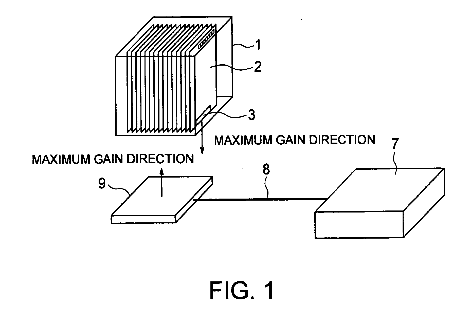
A first embodiment of the present invention will now be described in conjunction with FIGS. 1 and 2. FIG. 1 shows an article container 1 in which a plurality of postal envelopes 2 as an article are arranged face to face with each other. The article container 1 containing the postal envelopes 2 such as registered mails is used when the postal envelopes are transferred from one post office to another. In FIG. 1, the internal postal envelopes 2 are shown visible through a side of the article container 1.

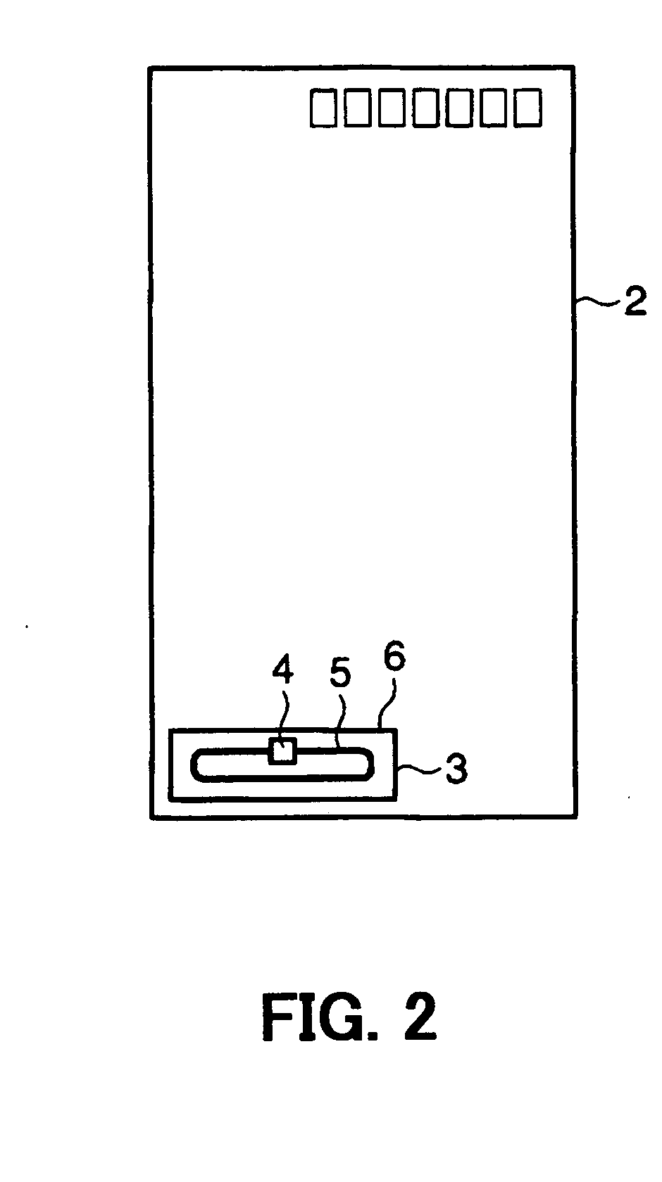
In FIG. 2, an RF tag 3 is affixed onto a surface of the postal envelope 2 at its lower left edge. This RF tag 3 is one commercially available on the market and is formed such that an IC chip 4 and a tag antenna 5 connected to the chip are wholly coated with coating material 6. The tag antenna 5 has a basic structure of, for example, either a dipole or folded-dipole antenna. The RF tag 3 does not carry a battery; the internal IC chip 4 is operated by the power that is obtained by dete...

second embodiment

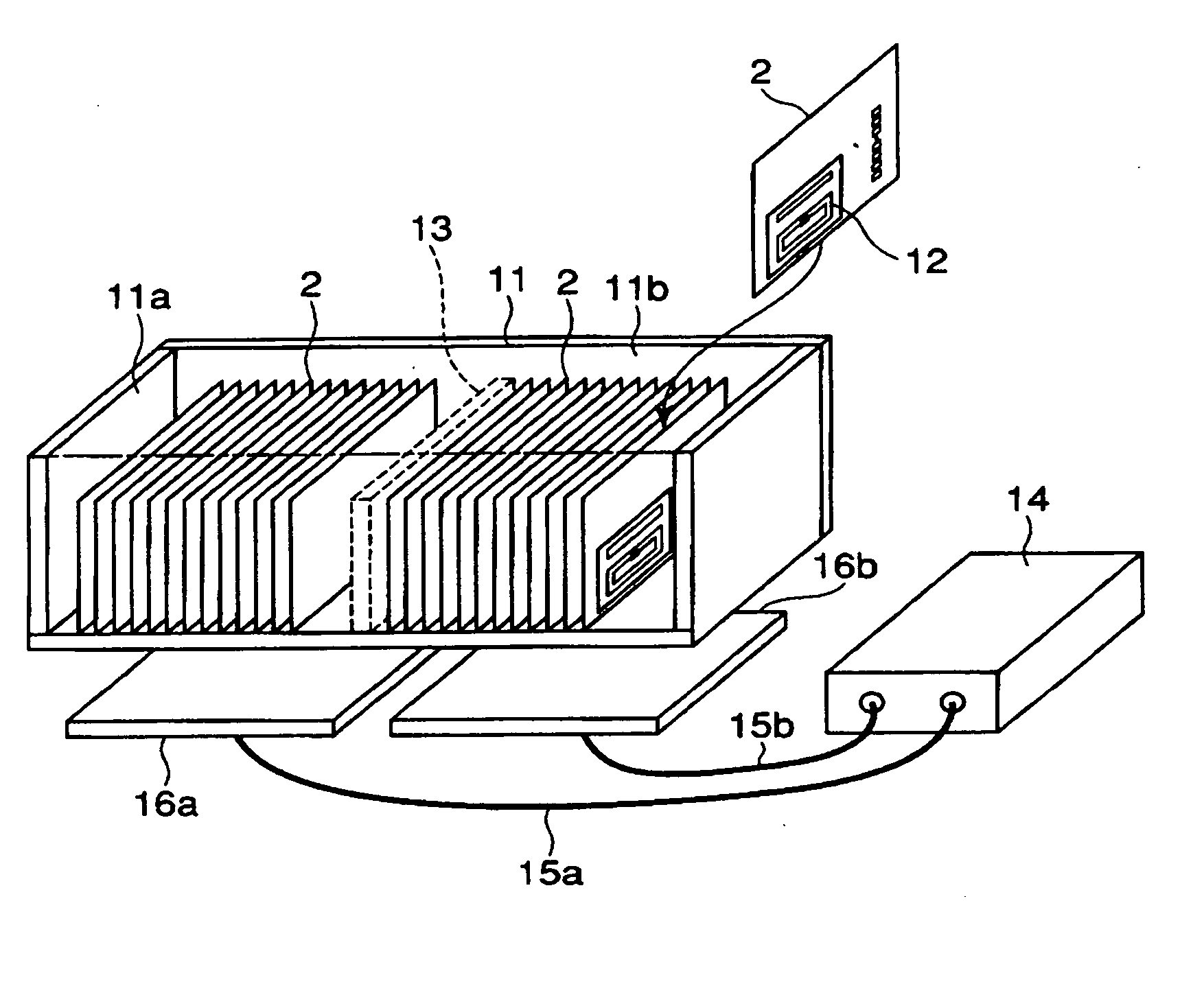
In FIGS. 3 and 4, the postal envelopes 2, each of which is provided with an RF tag module 12 that comprises the RF tags 3 and a reflector 17, are arranged sideways face to face with each other within an article container 11. Each RF tag module 12 is affixed to the postal envelope 2 in the vicinity of one side edge of the postal envelope 2. FIG. 3 shows the structure in a state wherein a front wall is removed so that the postal envelopes 2 contained in the article container 11 can be seen.

The article container 11 is internally partitioned into two compartments 11a and 11b by a partition board 13. A reader antennas 16a and 16b are disposed under basal planes of the compartments 11a and 11b, respectively. Reader antennas 16a and 16b are planar square-antenna. An interrogator 14 is connected to the reader antennas 16a and 16b via coaxial cables 15a and 15b, respectively. Since an RF tag reading apparatus comprising the reader antenna 16a and the compartment 11a is identical to an app...

third embodiment

As shown in FIG. 16, the article container 11 is partitioned into compartments 11a and 11b, and base plates 31 and 32, each of which is concaved upward and bent relative to a line of arranging the postal envelopes 2, are disposed. A plurality of the postal envelopes 2 are contained and arranged face to face with each other in the container on the concaved surface of the base plates 31 and 32. Hereinafter, since an RF tag reading apparatus structured by the reader antenna 16a and the compartment 11a having the base plate 31 is similar to that structured by the reader antenna 16b and the compartment 11b having the base plate 32, description thereof will be made only for the latter apparatus. The reader antenna 16b is disposed so that a center of the base plate 32, at the lowest thereof, and a center of the reader antenna 16b correspond to each other. Positional relation between the reader antenna 16b and the RF tags affixed to the respective postal envelopes 2 is such that a maximum ...


PUM


Abstract

An RF tag reading apparatus reads information from RF tags affixed to postal envelopes by a single operation. An article container contains a large number of postal envelopes provided with RF tags. A reader antenna, which is connected to an interrogator via a coaxial cable, is disposed under the article container. Maximum gain directions of the RF tags of the respective postal envelopes are uniformly directed to the reader antenna. The respective postal envelopes contained in the article container are arranged face to face with each other in a direction orthogonal to the maximum directions of the RF tags. Since a maximum gain direction of the reader antenna is oriented toward a base end surface of the article container, the maximum gain directions of the RF tags are opposed to the maximum gain direction of the reader antenna.

Description

CROSS REFERENCE TO RELATED APPLICATIONS This application is based upon and claims the benefit of priority from the prior Japanese Patent Application Nos. 2003-349827 filed on Oct. 8, 2003, and 2003-400265 filed on Nov. 28, 2003, the contents of which are incorporated herein by reference. BACKGROUND OF THE INVENTION 1. Field of the Invention The present invention relates, in general, to an RF tag reading apparatus using a container for containing a plurality of articles to each of which an RF tag is affixed. In particular, the invention relates to an RF tag reading apparatus which reads data from the RF tags of the respective articles regularly contained in the container. 2. Description of Related Art Japanese patent application Kokai publication No. 2002-37425 discloses an apparatus that contains in a container a plurality of articles, for example, registered mails, with RF tags attached thereto, and reads data from the RF tags of the respective registered mails by an interroga...

Claims


Application Information

Patent Timeline
IPC IPC(8): G06K7/10G06K17/00G06K19/07G06K19/077
CPCG06K7/0008G06K7/10316G06K7/10346G06K19/07796G06K19/0723G06K19/07749G06K19/07786G06K7/10554
Inventor OISHI, SADATOSHIKATO, MASAKAZUMATSUSHITA, NAOHIROSANO, KOICHIMUROFUSHI, NOBUOMATSUMOTO, YASUO
Owner TOSHIBA TEC KK
Why Eureka
Try Eureka