Imager exposure, illumination and saturation controls in a point-of-transaction workstation

a technology of illumination and saturation control and workstation, applied in the direction of exposure control, instruments, sensing by electromagnetic radiation, etc., can solve the problems of sluggish workstation performance, perceived defects, and variable symbol location in advance, so as to improve processing performance, shorten illumination time, and add complexity and undue expense to the workstation

Active Publication Date: 2013-01-31
SYMBOL TECH LLC
View PDF0 Cites 15 Cited by
  • Summary
  • Abstract
  • Description
  • Claims
  • Application Information

AI Technical Summary

Benefits of technology

[0011]In a preferred embodiment, a first proximity system is mounted on a first printed circuit board at one side of the housing and detects the product entering the field of view in a first direction, and a second proximity system is mounted on a second printed circuit board at an opposite side of the housing and detects the product entering the field of view in a second direction that intersects the first direction. Both first and second proximity systems emit and sense light through the at least one window, e.g., the horizontal window, and can thus detect whether the product is entering the workstation from the right side or from the left side of the workstation. A third proximity system is mounted on a third printed circuit board and is operative for detecting entry of the product in a third direction by emitting and sensing light through the other window, e.g., the upright window, and can thus detect whether the product is forwardly or rearwardly entering the workstation.
[0012]Thus, the intensity level of the return infrared light in each of these directions is sensed by its own individually dedicated proximity system. The illumination time of each illuminator in each illuminated subfield of view and / or the exposure of each imager are either separately or jointly adjusted. The proximity system has heretofore only been used for product detection and for activating the illumination system. According to this invention, the proximity system is used for additional purposes, i.e., to adjust the illumination time and / or the imager exposure. No longer need such workstations rely on internal auto-exposure circuits that adjust the exposure of the imager after a few frames have elapsed. No longer need such workstations be characterized as sluggish or defective. Processing performance is enhanced, all without adding additional complexity and undue expense to the workstation.
[0013]It is further advantageous to store a plurality of predefined intensity level thresholds for the sensed return infrared light in the controller, and to have the controller adjust the illumination time and / or the exposure by comparing the sensed return infrared light from the product in real time operation with these predefined thresholds. Thus, the threshold for reading indicia in a near range of working distances close to a respective window will be set to a shorter illumination time as compared to reading indicia in a far range of working distances remote from the respective window; otherwise, the sensed return illumination light will be too bright and will blind or saturate the imager. An illumination time and / or exposure suitable for reading indicia in a near range of working distances will not be suitable for reading indicia in a far range of working distances, and vice versa. This invention therefore also proposes to store a predefined illumination time and / or exposure that are associated with, and assigned to, each stored predefined threshold in the controller. Upon determination of the level of the sensed return infrared light from the product in real time operation, the assigned predefined stored illumination time and / or exposure are used, thereby increasing the responsiveness of the workstation and / or decreasing any performance dead areas in the scan zone arising from too much, or too little, intensity of the return illumination light.

Problems solved by technology

All these factors make the symbol location variable and difficult to predict in advance.
This non-negligible time delay creates a sluggishly performing workstation and may, in some cases, even be perceived as defective.

Method used


Image

  • Imager exposure, illumination and saturation controls in a point-of-transaction workstation
  • Imager exposure, illumination and saturation controls in a point-of-transaction workstation
  • Imager exposure, illumination and saturation controls in a point-of-transaction workstation

Examples


Embodiment Construction

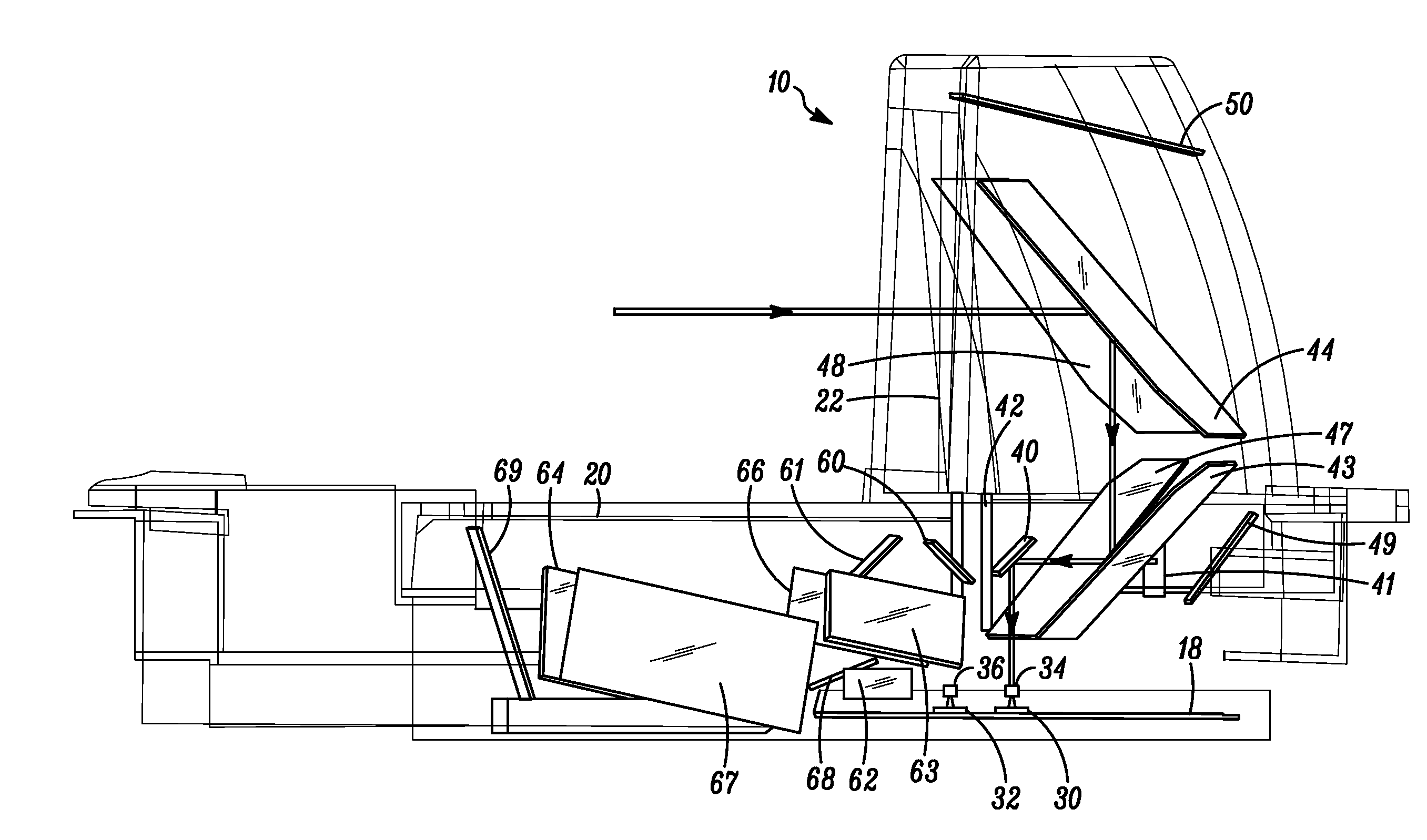
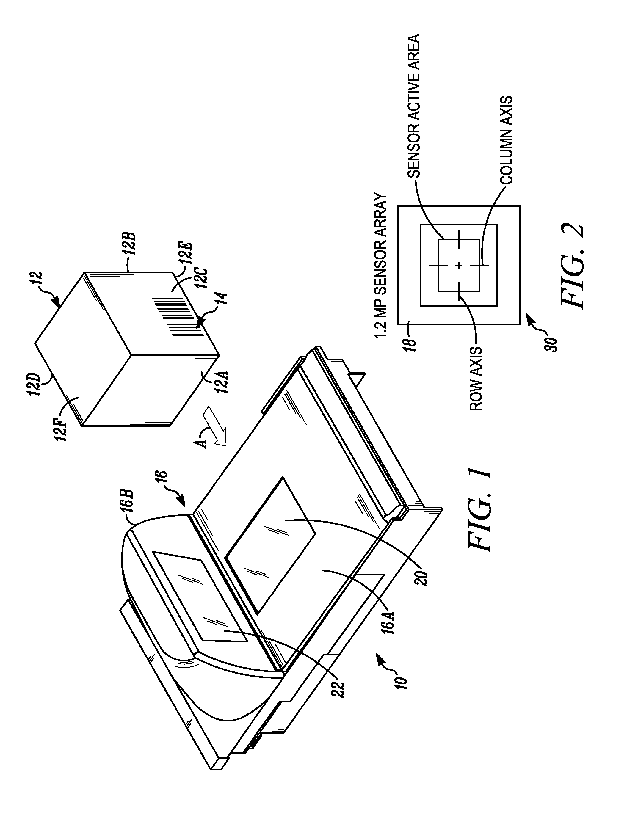
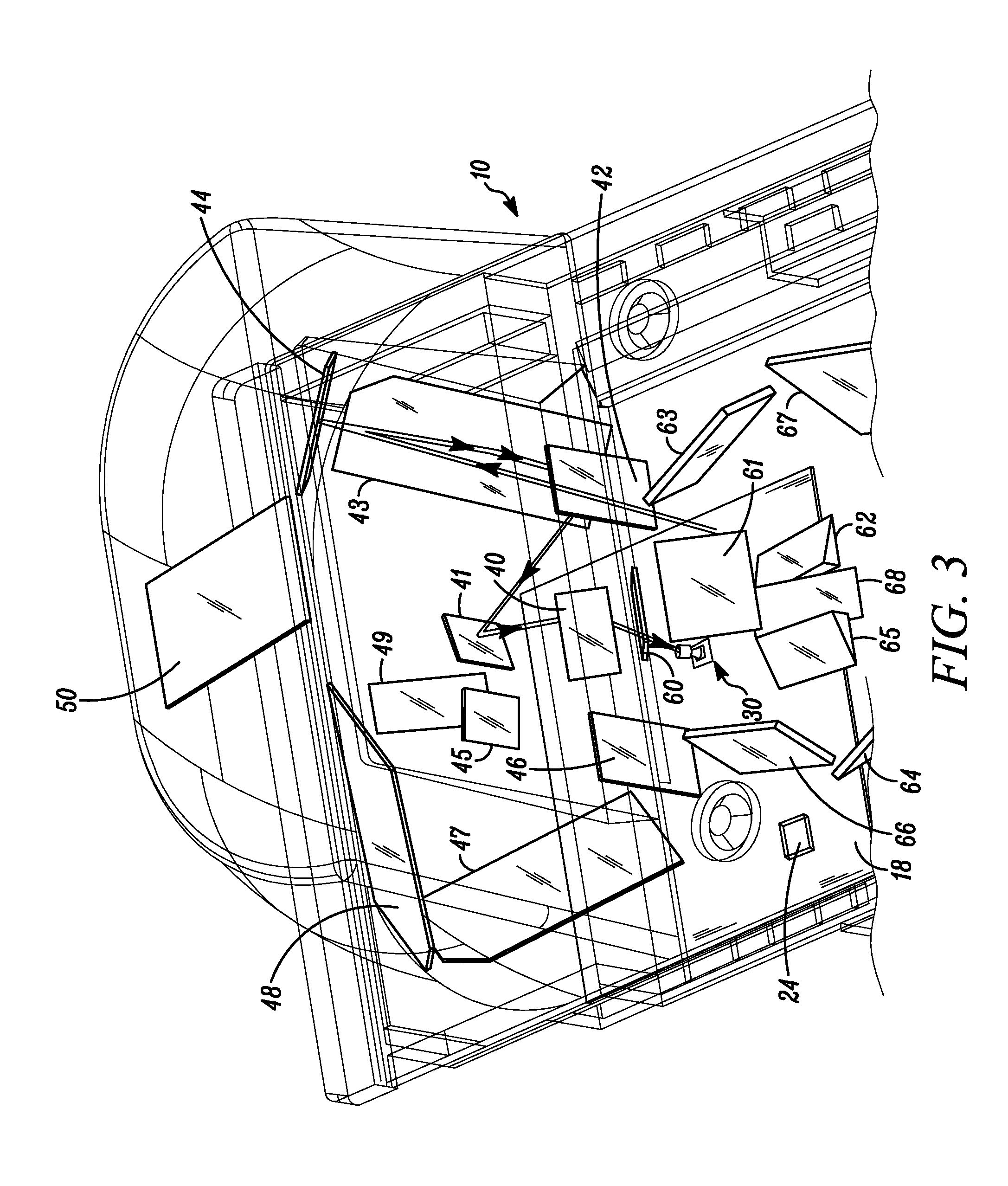
[0033]FIG. 1 depicts a dual window, bi-optical, point-of-transaction workstation 10 for electro-optically imaging indicia 14 or targets, such as the illustrated UPC symbol described above, associated with multi-sided, three-dimensional products 12, and is typically used by retailers to process transactions involving the purchase of the products 12 bearing, or printed with, the identifying indicia 14. The workstation 10 includes a housing 16 having a generally horizontal window 20 located in a generally horizontal plane and supported by a horizontal housing portion 16A, and an upright window 22 located in a generally upright plane that intersects the generally horizontal plane and supported by a raised housing portion 16B. The upright plane may lie in a vertical plane, or be slightly rearwardly or forwardly inclined relative to the vertical plane. The upright window 22 is preferably recessed within its housing portion 16B to resist scratching. By way of numerical example, the general...


PUM


Abstract

An illumination time of an illumination system and/or an exposure setting of an imaging system are adjusted by a proximity system operative for detecting a product entering a field of view in a bi-optical, dual window, point-of-transaction workstation. The proximity system includes an infrared emitter for emitting infrared light to the product, and an infrared sensor for sensing return infrared light from the product. Multiple predefined thresholds are stored for the sensed return infrared light, and a predefined illumination time and/or exposure setting are stored and assigned to each predefined threshold. Adjustment of the illumination time and/or of the exposure setting is performed by comparing the sensed return infrared light from the product in real time operation with the stored predefined thresholds.

Description

BACKGROUND OF THE INVENTION[0001]It is known to use laser-based and / or imager-based readers or scanners in a dual window or bi-optical workstation to electro-optically read indicia, such as bar code symbols, associated with three-dimensional products to be identified and processed, e.g., purchased, at a point-of-transaction workstation provided at a countertop of a checkout stand in supermarkets, warehouse clubs, department stores, and other kinds of retailers. The products are typically slid or moved in various directions by a user across, or presented to a central region of, a generally horizontal window that faces upwardly above the countertop and / or a generally vertical or upright window that rises above the countertop. When at least one laser scan line generated by a laser-based reader sweeps over a symbol and / or when return light from a symbol is captured over a field of view by a solid-state imager of an imager-based reader, the symbol is then processed, decoded and read, the...

Claims


Application Information

Patent Timeline
Patent Type & Authority Applications(United States)
IPC IPC(8): G06K7/14G06K7/01
CPCG06K7/10722G06K7/10732G06K7/10752G06K7/1096
Inventor CHEN, CAIHUAWITTENBERG, CARLTAN, CHINHSTEELE, MICHAELFRATIANNI, EDMOND L.DRZYMALA, MARKBARKAN, EDWARD
Owner SYMBOL TECH LLC
Why Eureka
Try Eureka