Optical recording medium, method of producing the same, and, optical recording method and optical reproducing method

a technology of optical recording and optical reproducing method, which is applied in the direction of optical recording/reproducing/erasing method, photomechanical apparatus, instruments, etc., can solve the problems of difficult to detect reproducing images when diffusion noise exists, the diffraction efficiency of one hologram is remarkably low, and the noise of diffusing light becomes more troublesome. , to achieve the effect of high density information and efficient read accuracy

Inactive Publication Date: 2007-03-08
FUJIFILM CORP +1
View PDF9 Cites 18 Cited by
  • Summary
  • Abstract
  • Description
  • Claims
  • Application Information

AI Technical Summary

Benefits of technology

[0013] It is an object of the present invention to solve the problems in the art described above and also to attain the purposes described below. That is, the purposes of the present invention are to provide optical recording media of hologram type capable of high-density recording and capable of preventing noise even when the informing light and the reference light leak from filter layers formed of wavelength-selective reflection films, methods of producing the optical recording media with higher efficiency and lower cost, as well as optical recording methods and optical reproducing methods that utilize the optical recording media.
[0015] The optical recording medium according to the present invention comprises the first substrate, the recording layer for recording information by use of holography, the filter layer, the optical absorption layer and the second substrate in this order, therefore, the selective reflection wavelength may be free from its shift even when the incident angle being changed, the informing light and the reference light utilized for recording and reproducing as well as the reproducing light are far from reaching the reflective film, therefore, the diffusing light due to diffuse reflection at the reflective surface may be prevented. Consequently, the noise due to this diffusing light may be free from detection by a CMO sensor or CDD in a condition duplicated with a reproducing image, thus the reproducing image may be detected in a level capable of error correcting. The noise of the diffusing light comes to be more troublesome as the multiplicity comes to higher. That is, when the multiplicity comes to higher, for example, to no less than 10, the diffraction efficiency by one hologram comes to remarkably lower, which makes very difficult to detect reproducing images when the diffusion noise exists. The present invention may make possible to remove such difficulty and to realize image recording with exceptionally high density. In addition, the optical absorption layer formed between the filter layer and the second substrate may make possible to absorb the recording light leaking from the filter layer thereby to reproduce reproductive images with less distortion.
[0018] In accordance with the inventive method of producing optical recording media, a filter layer of a laminated body of laminated cholesteric liquid crystal layers is provided on the second substrate. As a result, the optical recoding media can be mass-produced with higher efficiency and lower cost by way of convenient processes such as spraying.
[0020] The optical recording method of the present invention may achieve exceptionally high density recording, by virtue that the informing light and the reference light are irradiated using the optical recording medium according to the present invention in a manner that the optical axis of the informing light coincides with the optical axis of the informing light, and information is recorded on the recording layer by means of the interference pattern generated by the interference between the informing light and the reference light.
[0022] In accordance with the inventive optical reproduction method described above, the interference pattern of the recording layer to which the information being recorded by the inventive optical recording method can be efficiently exactly read thereby to reproduce the high density information.

Problems solved by technology

The noise of the diffusing light comes to be more troublesome as the multiplicity comes to higher.
That is, when the multiplicity comes to higher, for example, to no less than 10, the diffraction efficiency by one hologram comes to remarkably lower, which makes very difficult to detect reproducing images when the diffusion noise exists.

Method used


Image

  • Optical recording medium, method of producing the same, and, optical recording method and optical reproducing method
  • Optical recording medium, method of producing the same, and, optical recording method and optical reproducing method
  • Optical recording medium, method of producing the same, and, optical recording method and optical reproducing method

Examples


first operative example

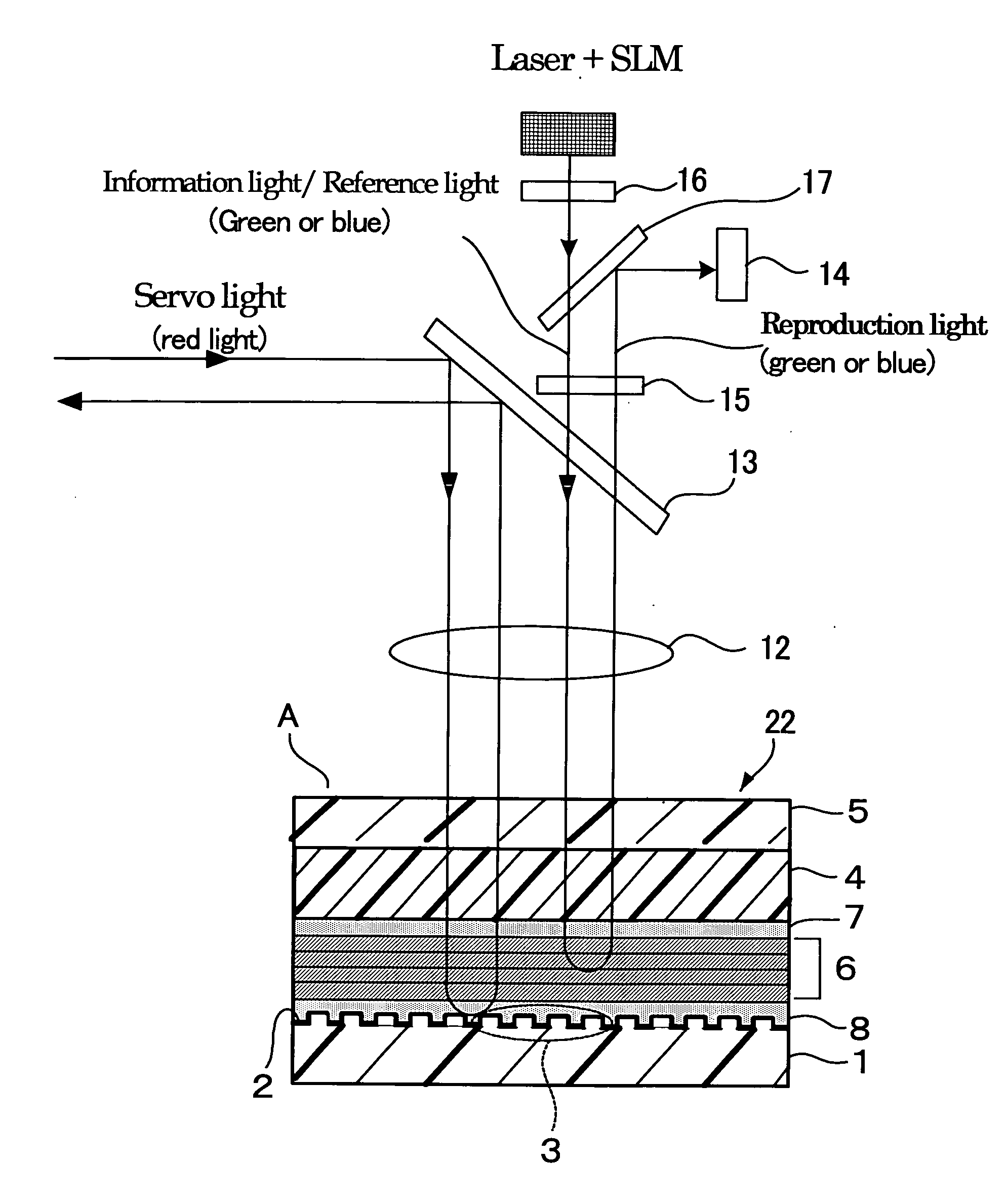
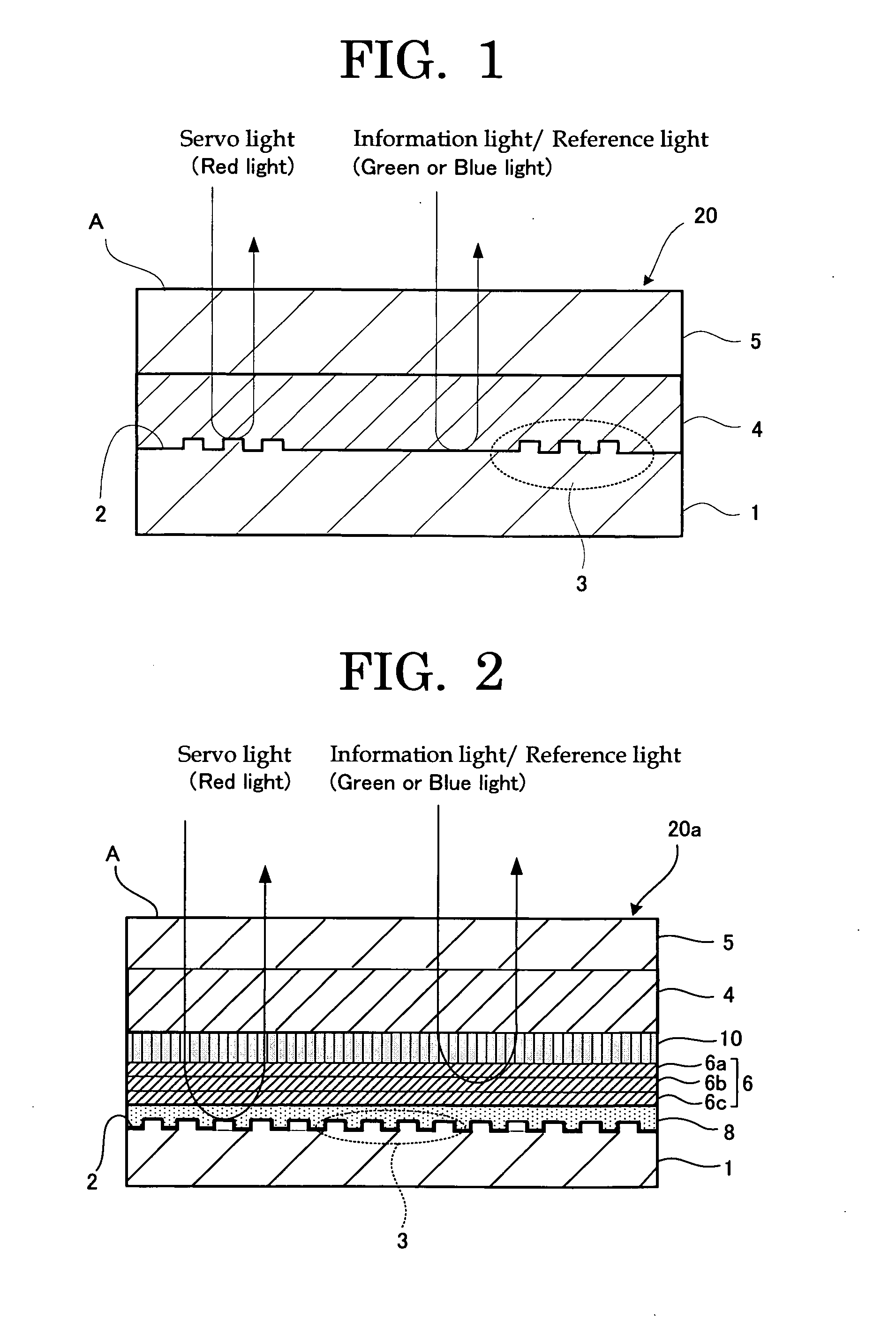
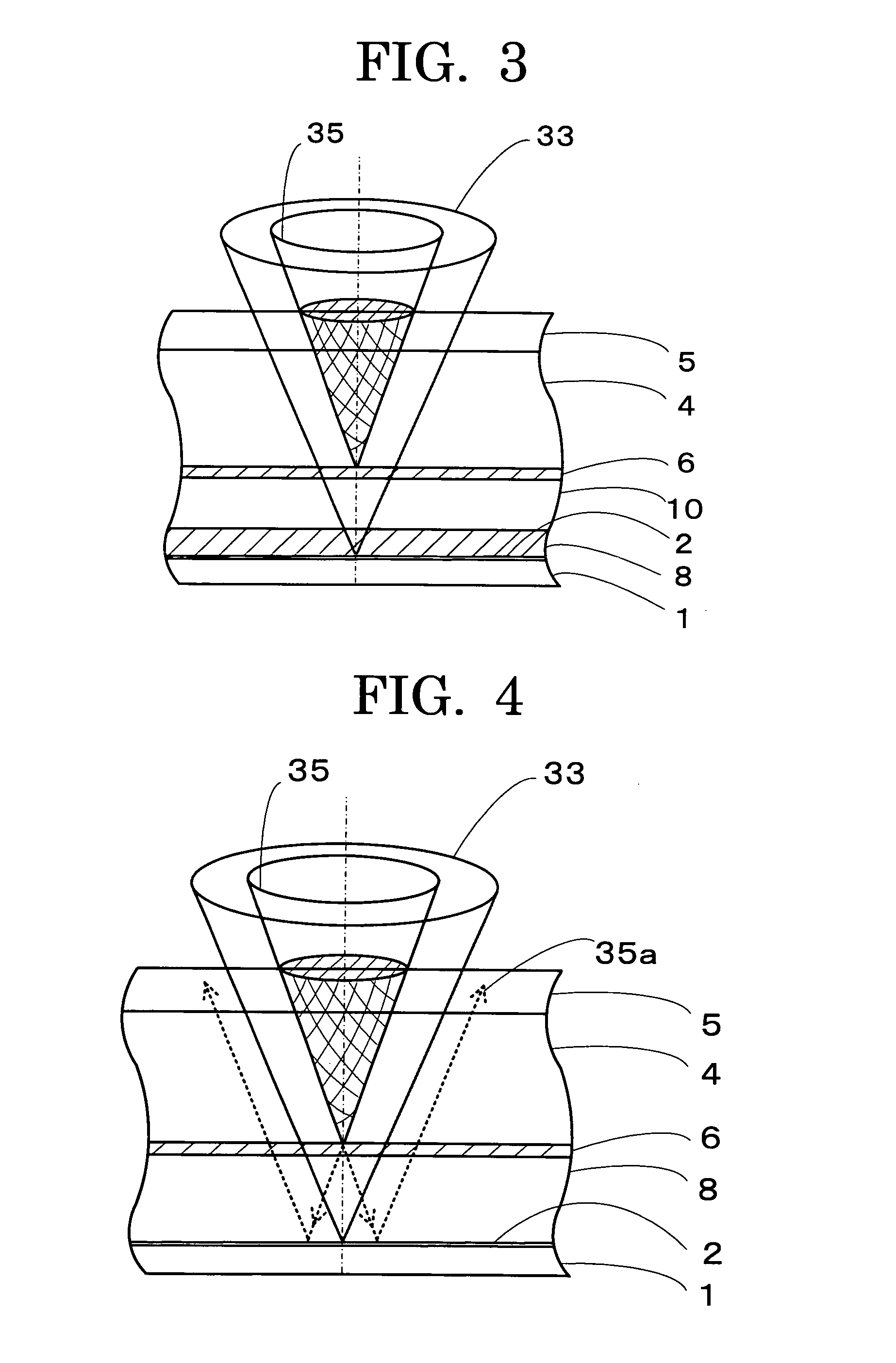
[0178]FIG. 7 is a schematic cross-sectional view showing the structure of the first Operative Example of the optical recording medium in the present invention. In the optical recording medium 21 according to the first Operative Example, servo pit pattern 3 is formed on the second substrate 1 made of a polycarbonate resin or glass, and the servo pit pattern 3 is coated with Al, Au, Pt or the like to form reflective film 2. Although the servo pit pattern 3 is formed on the entire surface of the second substrate 1 in FIG. 7, it may be formed on the second substrate 1 periodically as shown in FIG. 1. In addition, the height of the servo pit pattern 3 is 1750 angstroms (175 nm) at maximum, which being significantly smaller than those of the other layers including the second substrate.

[0179] The optical absorption layer 9 is formed by way of coating a material of screen printing ink etc. on the reflective film 2 of the second substrate 1 by screen printing and spin coating etc.

[0180] Th...

second operative example

[0190]FIG. 9 is a schematic cross-sectional view showing the configuration of the second Operative Example of the inventive optical recording medium. In the optical recording medium 23 of the second Operative Example, servo pit pattern 3 is formed on the second substrate 1 made of polycarbonate resin or glass, and the servo pit pattern 3 is coated with Al, Au, Pt or the like to form the reflective film 2. The height of the servo pit pattern 3 is usually 1750 angstroms (175 nm), which being similar with the first Operative Example.

[0191] The difference between the first Operative Example and the second Operative Example is that the first gap layer 8 is disposed between the second substrate 1 and the filter layer 6 and the optical absorption layer 9 is formed between the first gap layer 8 and the filter layer 6 in the optical recording medium 23 of the second Operative Example. More specifically, the difference is that the first gap layer 8 entirely corresponds to the optical absorpt...

example 1

—Preparation of Filter for Optical Recording Medium—

[0230] A filter was prepared as a filter for optical recording media, which consisting of a dielectric vapor deposition layer formed by laminating alternatively plural layers of a dielectric thin layer having a higher refractive index and a dielectric thin layer having a lower refractive index.

[0231] The material of the dielectric thin layer having a higher refractive index was TiO2, the material of the dielectric thin layer having a lower refractive index was TiO2; nine layers of these materials were alternatively laminated as TiO2 / SiO2 / TiO2 / SiO2 / TiO2 / SiO2 / TiO2 / SiO2 / TiO2 by means of DC oxygen reactive sputtering. Each of the layers was 532 nm / 4n, in which “n” being 2.5 in TiO2 and 1.5 in SiO2.

Evaluation of Optical Reflective Property

[0232] The resulting filter for optical recording media was determined in terms of the optical reflective property using a spectral reflection meter (optical source: L-5662 by Hamamatsu Photonics K...


PUM

PropertyMeasurementUnit
wavelengthaaaaaaaaaa
thicknessaaaaaaaaaa

Abstract

The present invention is intended to provide optical recording media of hologram type capable of high-density recording and capable of preventing noise even when the informing light and the reference light leak from filter layers formed of wavelength-selective reflection films. Accordingly, the present invention relates to optical recording media has a first substrate, a recording layer, a filter layer, an optical absorption layer and a second substrate in this order, wherein the recording layer records information by use of holography; methods of producing the same, as well as optical recording methods for the recording media and optical reproducing methods. Preferably, the optical absorption layer absorbs a light having a wavelength within 350 nm to 600 nm and transmits a light having a wavelength within 600 nm to 900 nm.

Description

BACKGROUND OF THE INVENTION [0001] 1. Field of the Invention [0002] The present invention relates to optical recording media, which being appropriately utilized for wavelength-selective reflection films in optical recording media of hologram type capable of high density image recording, methods of producing the optical recording media, as well as optical recording methods and optical reproducing methods that utilize the optical recording media. [0003] 2. Description of the Related Art [0004] One type of recording media capable of recording large amounts of information e.g. high-density image data is optical recording media. These optical recording media have been commercially introduced, for example, in a form of rewritable optical recording media such as optical magnetic discs and phase change optical discs and in a form of recordable optical recording media such as CD-Rs. These optical recording media have been limitlessly demanded for their still larger capacity. However, all of ...

Claims


Application Information

Patent Timeline
Patent Type & Authority Applications(United States)
IPC IPC(8): G03F7/00G11B7/00G11B7/24G11B7/24044G11B7/24062G11B7/246G11B7/2467G11B7/247G11B7/2472G11B7/249G11B7/253G11B7/2531G11B7/2533G11B7/2534G11B7/2536G11B7/258G11B7/2585G11B7/2595
CPCG11B7/0065G11B7/26G11B7/1275G11B7/24044G11B7/24062G11B7/2467G11B7/2472G11B7/248G11B7/249G11B7/252G11B7/2531G11B7/2533G11B7/2534G11B7/2536G11B7/256G11B7/2585G11B7/2595G11B7/00781
Inventor USAMI, YOSHIHISA
Owner FUJIFILM CORP
Why Eureka
Try Eureka