Electric parking brake system and control method for the electric parking brake

a technology of electric parking brake and control method, which is applied in the direction of brake cylinder, anti-theft devices, braking systems, etc., can solve the problems of low power consumption efficiency and achieve the effect of high efficiency and steady braking for

Inactive Publication Date: 2005-04-14
ASMO CO LTD
View PDF9 Cites 51 Cited by
  • Summary
  • Abstract
  • Description
  • Claims
  • Application Information

AI Technical Summary

Benefits of technology

[0006] An object of the present invention is to provide an electric parking brake system capable of ...

Problems solved by technology

However, the above-described conventional control method has a problem in that even when the temperature of the friction member is not in the temperature range in which the braking force decrea...

Method used


Image

  • Electric parking brake system and control method for the electric parking brake
  • Electric parking brake system and control method for the electric parking brake
  • Electric parking brake system and control method for the electric parking brake

Examples


Embodiment Construction

[0016] One embodiment embodying the present invention will now be described with reference to the accompanying drawings.

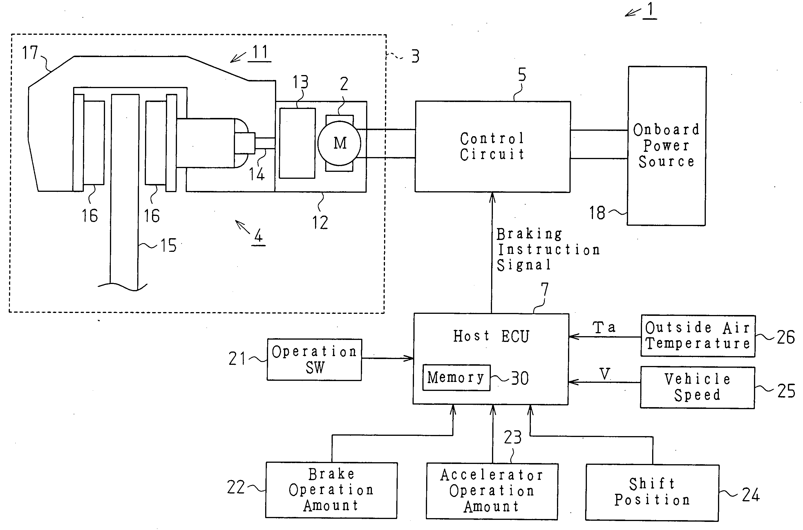
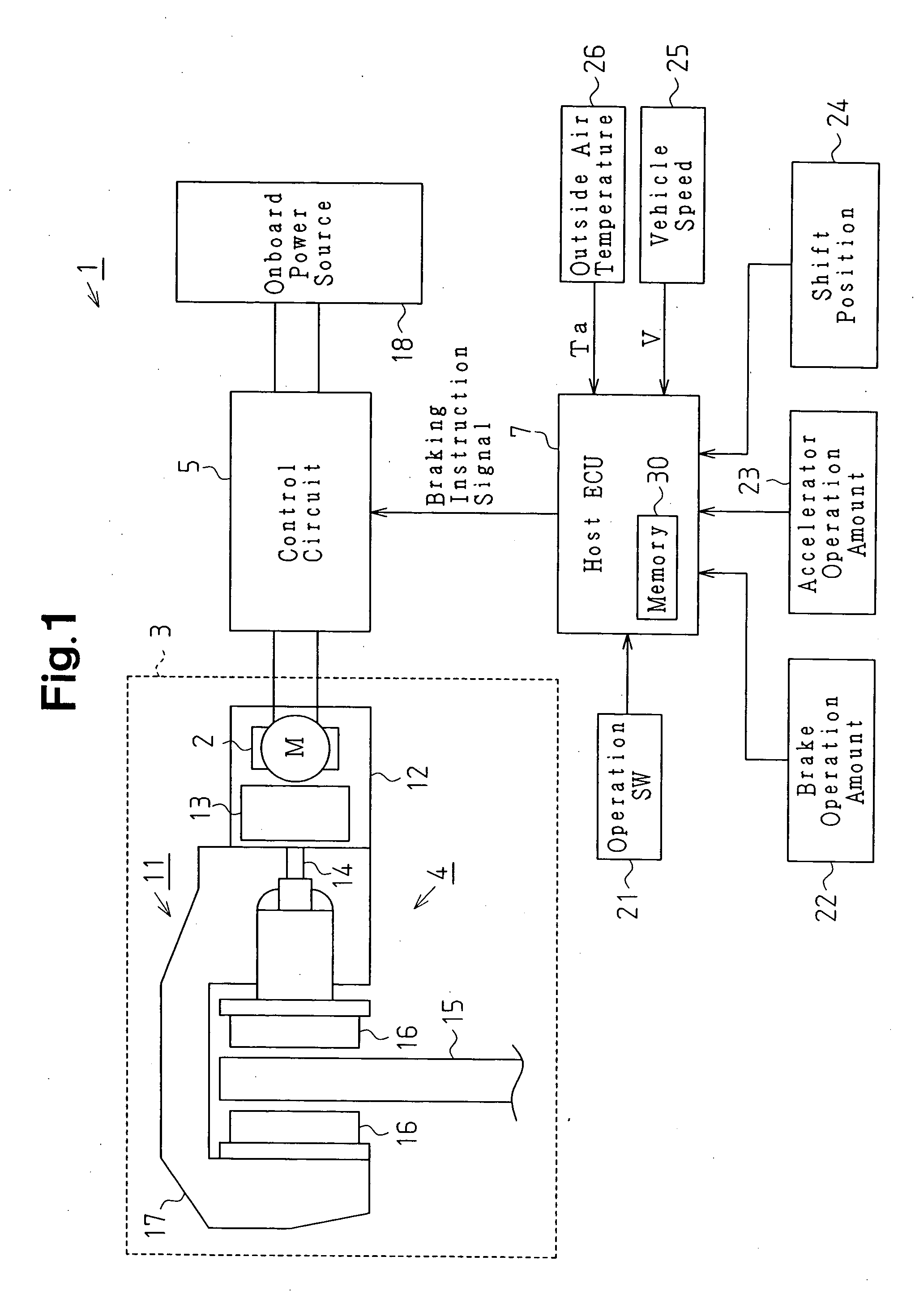
[0017] As shown in FIG. 1, an electric parking brake system 1 in accordance with this embodiment includes an electric parking brake 4 for giving a braking force to a wheel 3 with a motor 2 being used as a power source, a control circuit 5 for controlling the operation of the motor 2, that is, the operation of the electric parking brake 4, and a host ECU 7 serving as a control means for instructing the control circuit 5 to generate the braking force by using the electric parking brake 4. The host ECU 7 and the control circuit 5 serve as a control section for controlling the motor 2.

[0018] The electric parking brake 4 has a braking section 11 provided on the wheel 3 to give a braking force to the wheel 3, and an actuator 12 for driving the braking section 11. The actuator 12 drives the braking section 11 by converting the normal / reverse rotation of the motor 2 into...


PUM


Abstract

A friction member driven by a motor is pressed against a rotating element that rotates integrally with a wheel to give a pressing force to the rotating element, thereby applying braking force to the wheel. Control means controls the control circuit that controls the motor. In order to apply braking force to the wheel, the control means commands the control circuit to drive the motor once or a plurality of times at a predetermined time interval. Determining means determines a temperature of the friction member at the time when the parking brake starts braking the wheel. Setting means sets at least one of the number of driving of the motor, the time interval, and the target value of the pressing force. Therefore, a steady braking force with high efficiency is generated.

Description

BACKGROUND OF THE INVENTION [0001] The present invention relates to an electric parking brake system and a control method for the electric parking brake. [0002] A vehicular parking brake system including an electric parking brake using a motor as a driving source gives a braking force to a wheel by pressing a friction member (pad or shoe) on a rotating element (rotor or drum) rotating integrally with the wheel. [0003] In this parking brake system, since the friction member and its support member (caliper or drum) have much different thermal expansion coefficients, when parking braking is performed in a state in which the friction member is hot due to heat generation caused by the braking operation during the running of a vehicle, the braking force decreases with time. When the friction member is always pressed on the rotating element with a strong pressing force considering such a decrease in braking force with time, the system becomes large in size to ensure rigidity capable of wit...

Claims


Application Information

Patent Timeline
IPC IPC(8): B60T8/00B60T7/02B60T7/10B60T7/12B60T13/74F16D55/26F16D65/18F16D66/00
CPCB60T7/107B60T7/12F16D2066/006B60T13/746B60T17/221B60T13/741
Inventor SUZUKI, HIDETOSHIINA, EIJI
Owner ASMO CO LTD
Why Eureka
Try Eureka