Energy transfer device for series connected energy source and storage devices

a technology of energy storage device and energy transfer device, which is applied in the direction of transportation and packaging, charging equalisation circuit, and arrangement of several simultaneous batteries, etc., can solve the problems of over-discharging and damage, reduce the capacity of the string, increase the size and cost of the balancing device, etc., and achieve increased energy storage capacity, increased power output, and increased life

Inactive Publication Date: 2005-04-14
NEAR TIMOTHY PAUL
View PDF10 Cites 185 Cited by
  • Summary
  • Abstract
  • Description
  • Claims
  • Application Information

AI Technical Summary

Benefits of technology

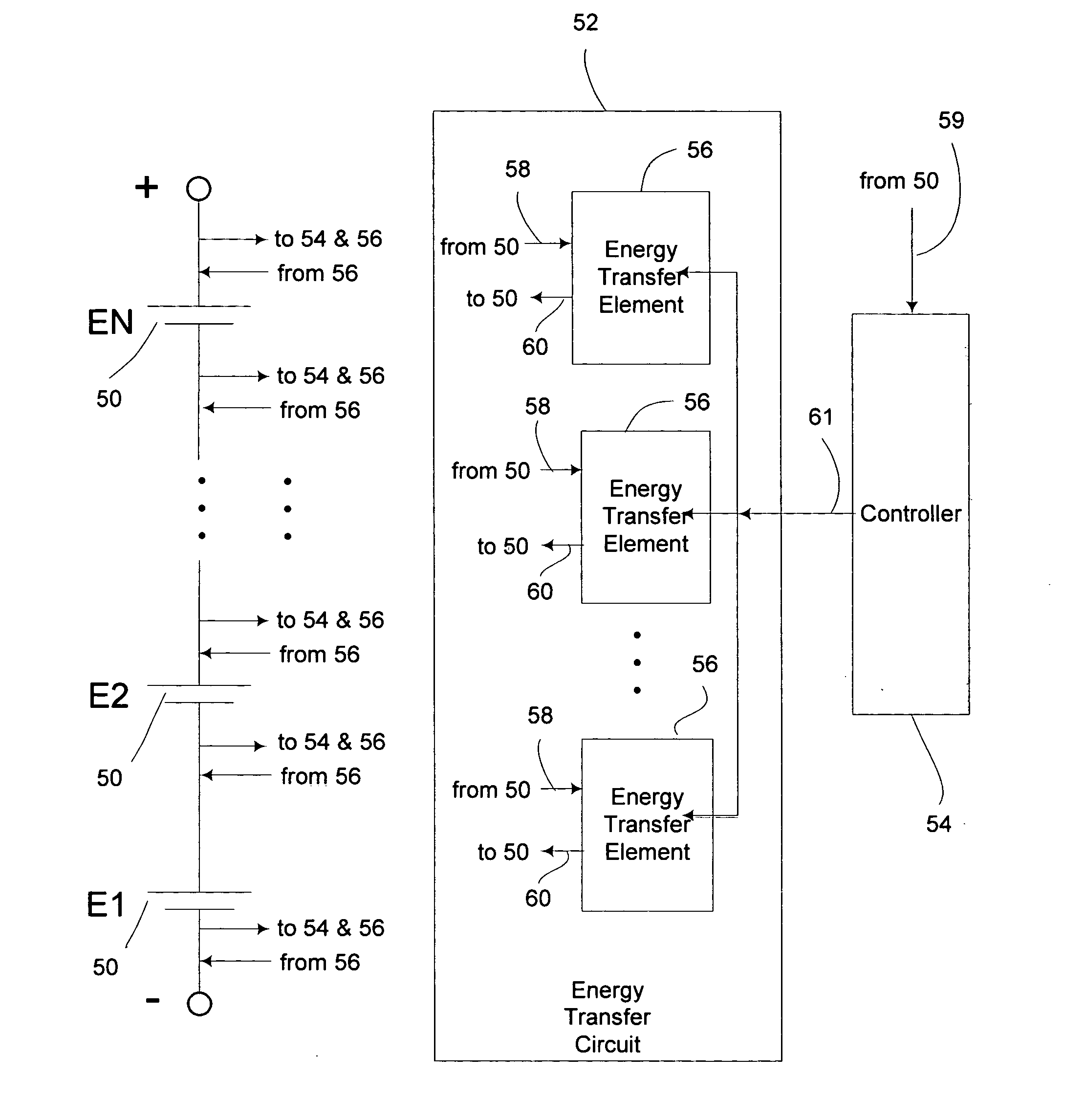
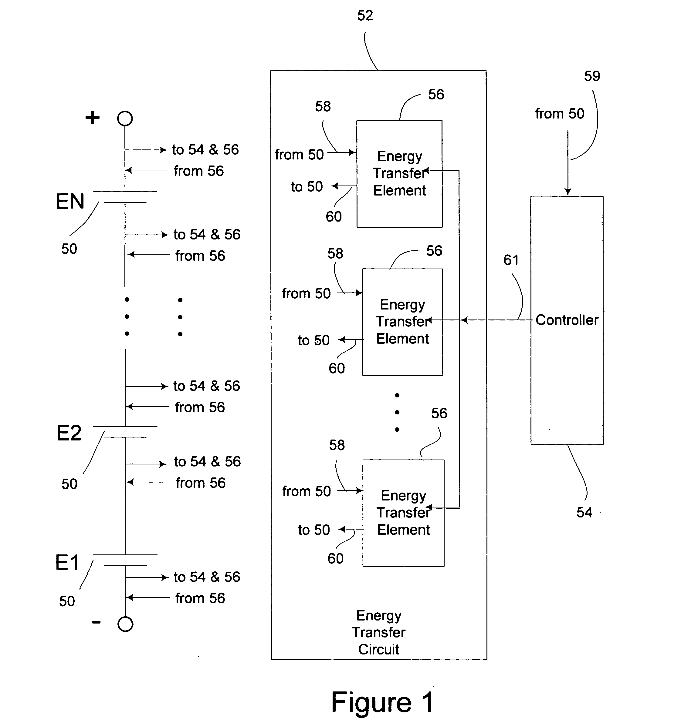
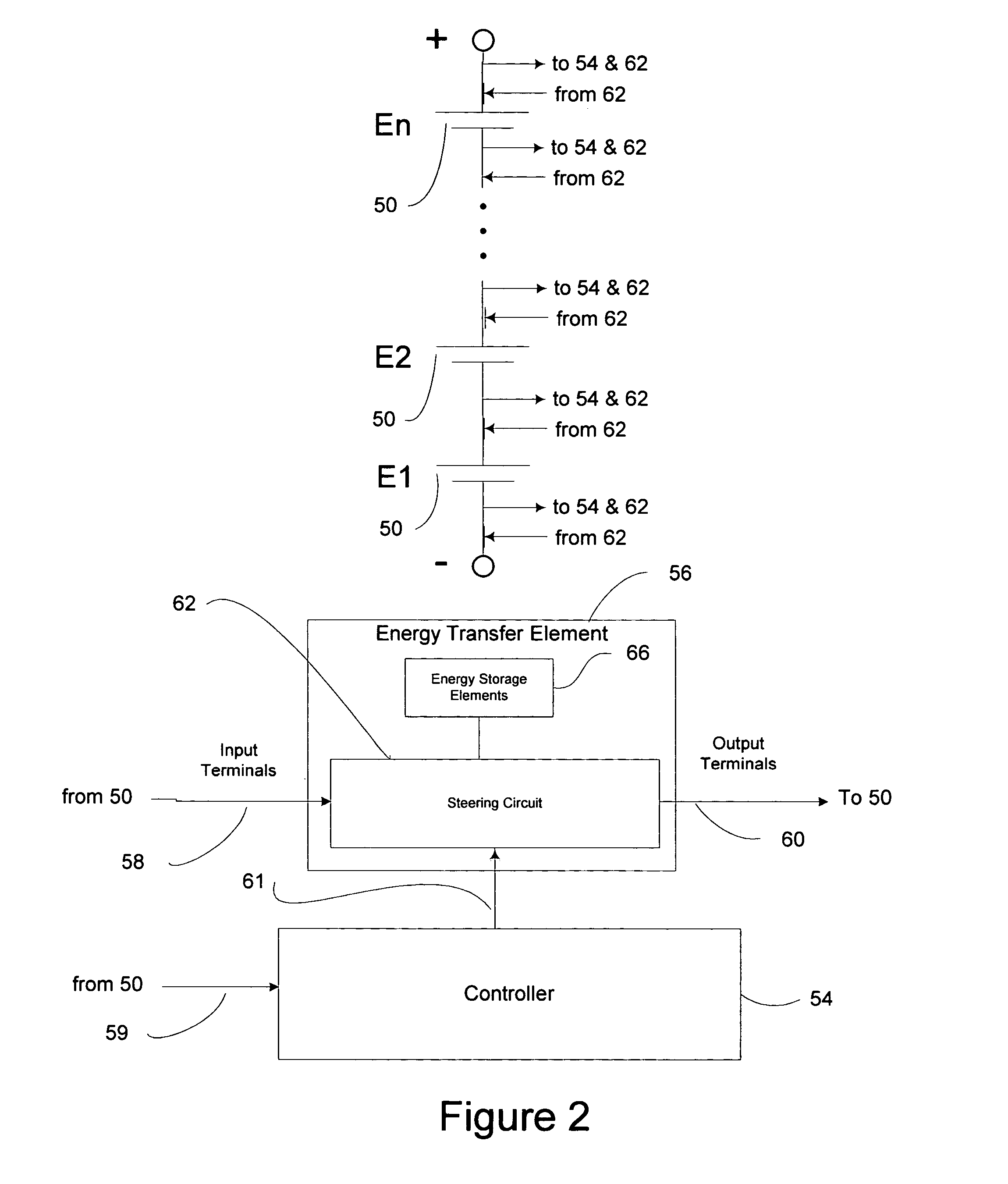
[0012] In accordance with the present invention, an energy transfer module is provided for series connected strings of energy source or storage devices. The energy transfer module is capable of transferring energy simultaneously from one or more energy source or storage devices to other energy devices in the string. By applying one or more modules to a string of energy devices and by modulating the various switches in the modules, energy is transferred among the energy devices. In this manner, the modules provide a means to adjust the charge or potential of each energy device in the series connected string. The modules may be used to balance charge in a string, which can provide benefits of increased lifetime, increased energy storage capacity, and increased power output.
[0013] The energy transfer module will generally include a controller that monitors the charge or potential of the series connected energy devices and provides control signals to the energy transfer circuit. A variety of algorithms may be used to accomplish charge transfer and achieve the specific type of balancing desired. Different systems and applications of these systems may result in a variety of energy transfer circuits, control circuits, and algorithms being employed.
[0014] A major improvement of the present invention as compared to previous devices is its ability to simultaneously transfer charge among multiple energy devices in a string. While much of the prior art is limited to the transfer of charge between two adjacent energy devices, the present invention discloses configurations that transfer energy between multiple devices, including nonadjacent groups of energy devices in the string. In a number of the configurations disclosed, energy is transferred among multiple devices with just a single switch. The means and methods disclosed allow the construction of energy transfer devices which provide faster, more efficient charge balancing at a lower cost than was previously available.
[0015] Another improvement is that the controller may include a temperature sensor that senses temperature in the module and reduces the rate of energy transfer at higher temperatures. This feature provides the benefit

Problems solved by technology

A disadvantage of this approach is that capacity of the string is reduced as energy drawn by the shunts is converted to heat and is not available to supply loads attached to the string.
This generally increases the size and cost of the balancing device.
Another disadvantage is that a shunt can cause over-discharging and damage unless it is disconnected when the energy device it is attached to is in a discharged or under voltage state.
While a simple control circuit may be used with this approach, it has significant drawbacks.
One serious disadvantage is that any mismatch between the characteristics of the secondary windings results in unbalanced voltages being applied to the batteries in the string.
It is difficult and relatively expensive to construct a transformer with multiple secondary windings matched closely enough to provide adequate charge balancing.
It is also difficult to maintain a close match between secondary windings across a range of operating conditions and throughout the life of the device.
Applying this type of charge balancing device to a string of batteries may not only provide inadequate balancing, it may actually cause a charge imbalance, thereby reducing battery life and runtime instead of improving it.
Another disadvantage

Method used


Image

  • Energy transfer device for series connected energy source and storage devices
  • Energy transfer device for series connected energy source and storage devices
  • Energy transfer device for series connected energy source and storage devices

Examples


Embodiment Construction

[0066]FIG. 5 illustrates one type of an energy transfer element 56 with one pair of input terminals and one pair of output terminals where one of the input terminals and one of the output terminals share a common terminal 68. The steering circuit consists of a single switch 70 and a single rectifier 72. The energy storage element 66 is an inductor. This energy transfer element transfers energy from one or more energy devices connected across input terminals 58 and 68 to one or more energy devices connected across output terminals 60 and 68. The energy devices to which charge is added are adjacent to and at a higher potential than the devices from which charge is removed. When connected to the string as shown in FIG. 5, this energy transfer element removes energy from the energy device 50b and transfers it to the energy devices 50c and 50d. When the switch 70 is closed, current ramps up in inductor 66, conducting through inductor 66, switch 70, and energy device 50b, thereby removing...


PUM


Abstract

A low cost, efficient, and rapid means for transferring energy or balancing charge among multiple, series connected batteries, capacitors, photovoltaic cells, fuel cells, and other types of energy source or storage devices is provided. Modules that transfer energy by moving charge from one or more series connected energy devices directly to one or more other energy devices in the string are disclosed. The modules utilize steering circuits comprised of switches and rectifiers, and energy storage elements such as inductors and transformers, to transfer energy between multiple energy devices in the string. The modules may be used in combination with string charging devices and loads. The modules provide a means to balance charge or potential of the energy devices, which is known to provide benefits of increased life and capacity.

Description

CROSS-REFERENCE TO RELATED APPLICATIONS [0001] This application is entitled to the benefit of Provisional Patent Application No. 60 / 511,053 filed Oct. 14, 2003.BACKGROUND [0002] 1. Field of the Invention [0003] This invention pertains generally to the field of power sources containing a number of energy source or storage devices connected in series, and specifically to circuits and methods for transferring or balancing energy, charge, or potential among series connected energy source or storage devices. [0004] 2. Description of Prior Art [0005] Many systems incorporate batteries, capacitors, photovoltaic cells, fuel cells and other energy devices connected in series. These systems include standby power supplies, electric motor drives, electric vehicles, uninterruptible power supplies, fuel cell systems, and photovoltaic systems. Balancing the charge, voltage potential, or energy of each series connected energy device is critical in many applications. The ability to transfer charge i...

Claims


Application Information

Patent Timeline
IPC IPC(8): H02J7/00
CPCH02J7/0018
Inventor NEAR, TIMOTHY PAUL
Owner NEAR TIMOTHY PAUL
Why Eureka
Try Eureka