Digital current limiter

a digital current limiter and current limiter technology, applied in the field of digital current control, can solve the problems of high current demands, complex and inflexible analog current limiters, and difficult implementation of logic control functionality with analog current limiters, and achieve the effect of easy setting and modification in softwar

Inactive Publication Date: 2005-04-14
HONEYWELL INT INC
View PDF21 Cites 53 Cited by
  • Summary
  • Abstract
  • Description
  • Claims
  • Application Information

AI Technical Summary

Benefits of technology

[0009] The digital controller receives the indication of the magnitude of the current and, in turn, controls the respective switch based on the magnitude of the current. Advantageously,

Problems solved by technology

However, analog current limiters are often complex and inflexible.
Further, implementing logic control functionality with analog current limiters is often difficult.
The new functions can often cause higher current demands that, in turn, may require

Method used


Image

  • Digital current limiter
  • Digital current limiter
  • Digital current limiter

Examples


Embodiment Construction

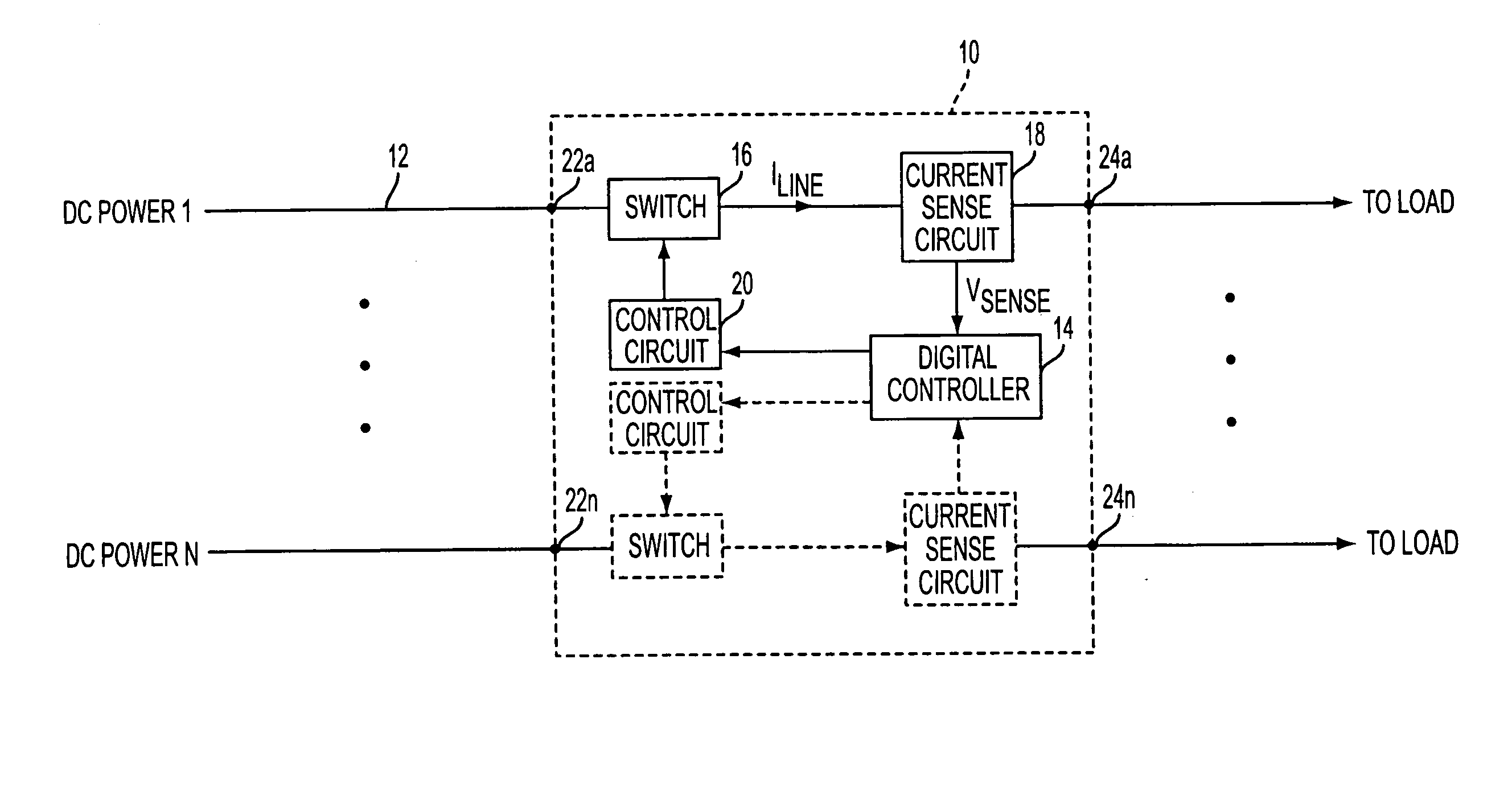
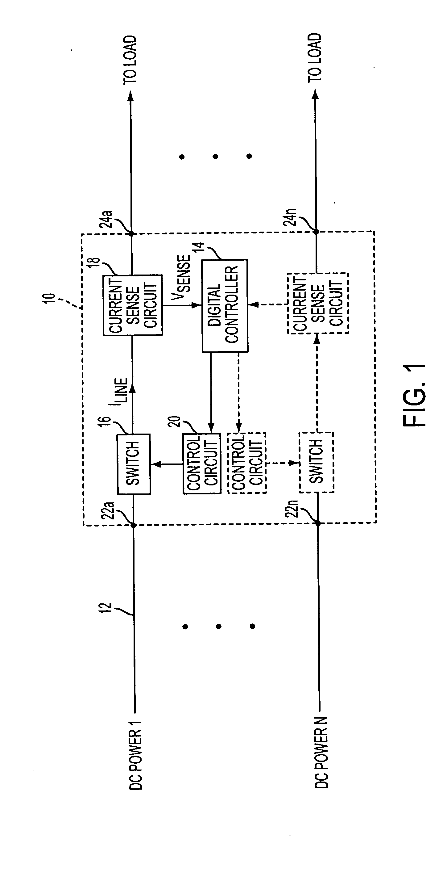
[0019] 1. Overview FIG. 1 is a simplified block diagram of a digital current limiter 10 in accordance with one disclosed embodiment of the present invention. As illustrated in FIG. 1, digital current limiter 10 includes one or more power inputs 22a-n and corresponding outputs 24a-n. Each of the power inputs 22a-n can be connected to a respective DC input power line, such as an input power line 12. As further shown in FIG. 1, digital current limiter 10 includes a digital controller 14 that can concurrently monitor and control current flowing from each of the one or more inputs 22a-n to the corresponding output 24 via a respective (i) switch (e.g., a switch 16), (ii) current-sense circuit (e.g., a current-sense circuit 18), and (iii) control circuit (e.g., a control circuit 20).

[0020] In operation, when switch 16 is “on” (i.e., closed), input power line 12 is electrically coupled to a load on output 24a. Resulting current ILINE flows to the load through current-sense circuit 18, whic...


PUM


Abstract

A digital current limiter is provided. The digital current limiter includes a microprocessor that is capable of monitoring and controlling multiple current flows concurrently. The microprocessor can be programmed with various current limits and current control functions than can be set and modified in software. In addition, by including a serial communication interface, the current limits and current control functions of the digital current limiter can be modified remotely.

Description

PRIORITY [0001] The present patent application claims priority under 35 U.S.C. § 119(e) to the U.S. Provisional Patent Application No. 60 / 510,066, filed on Oct. 9, 2003, entitled “Digital Current Limiter,” to Harrington, the full disclosure of which is incorporated herein by reference.BACKGROUND [0002] 1. Field of Invention [0003] The present invention relates to electrical current control and, more particularly, to digital current control, and extends to digital power control because of the ability to digitally control current. [0004] 2. Description of Related Art [0005] For many applications, it is important to control the current flow in a circuit using a current limiter. For example, it may be desirable to limit current flow from a power supply to an electrical appliance to prevent damage to the appliance by current overload. Traditionally, current limiting is accomplished with analog circuits. However, analog current limiters are often complex and inflexible. To modify function...

Claims


Application Information

Patent Timeline
IPC IPC(8): H02J1/08H02J1/14H02J7/00H03M1/12
CPCH02J1/08H02J7/0031H02J1/14H02J7/00304
Inventor HARRINGTON, JAMES B.
Owner HONEYWELL INT INC
Why Eureka
Try Eureka