Objective lens for optical pick-up

a technology of optical pick-up and objective lens, which is applied in the direction of optical beam sources, instruments, data recording, etc., can solve the problems of not being configured to support the hd dvd, the reproduction of data of the hd dvd cannot be formed, and the cd cannot be formed, etc., and achieve the effect of diffraction efficiency

Inactive Publication Date: 2005-04-14
HOYA CORP
View PDF4 Cites 45 Cited by
  • Summary
  • Abstract
  • Description
  • Claims
  • Application Information

AI Technical Summary

Benefits of technology

[0036] With this configuration, the second region can function as a filter configured such that the diffraction efficiency for the first and se

Problems solved by technology

However, the objective lens disclosed in the publication No. 2000-81566 is not configured to support the HD DVD.
That is, when the blue laser beam is incident on the objective lens disclosed in the publication, aberrations including a spherical aberration are caused and therefore a beam spot suitable for the recordation and the reproduction of data o

Method used


Image

  • Objective lens for optical pick-up
  • Objective lens for optical pick-up
  • Objective lens for optical pick-up

Examples


first example

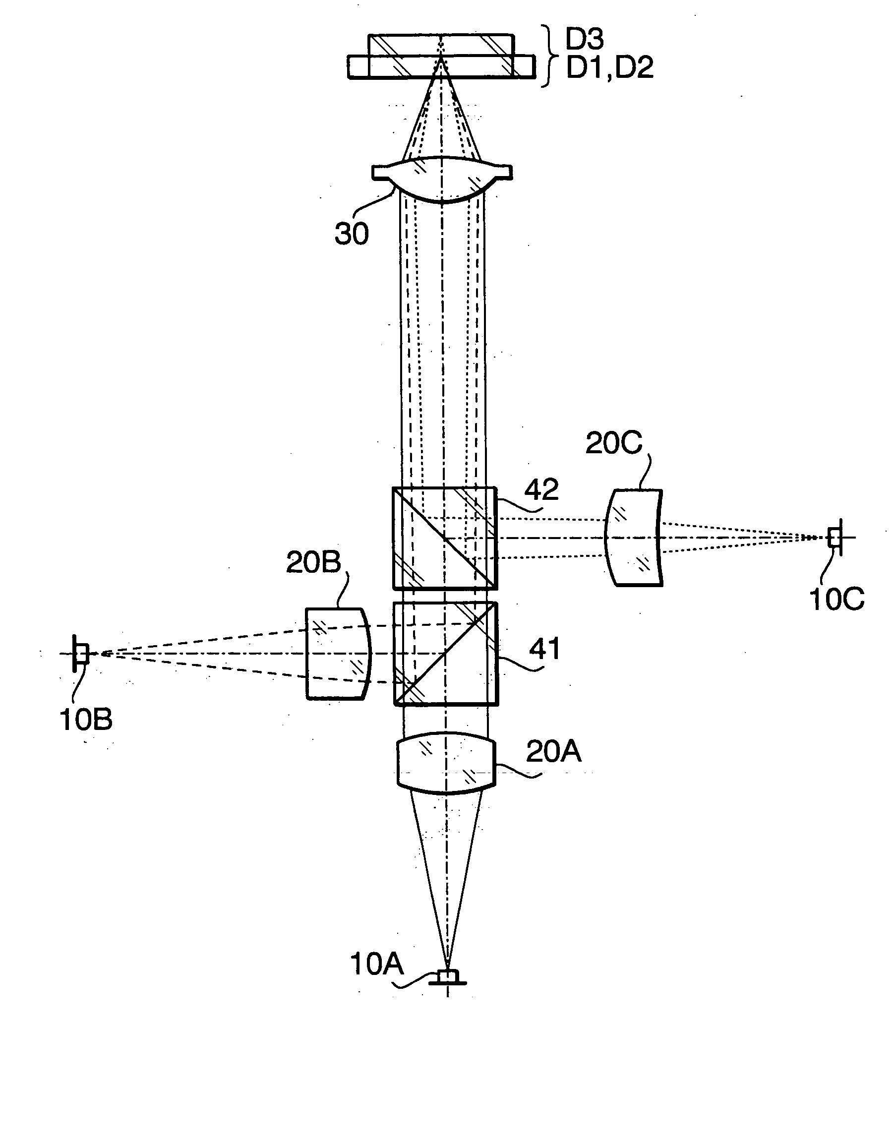
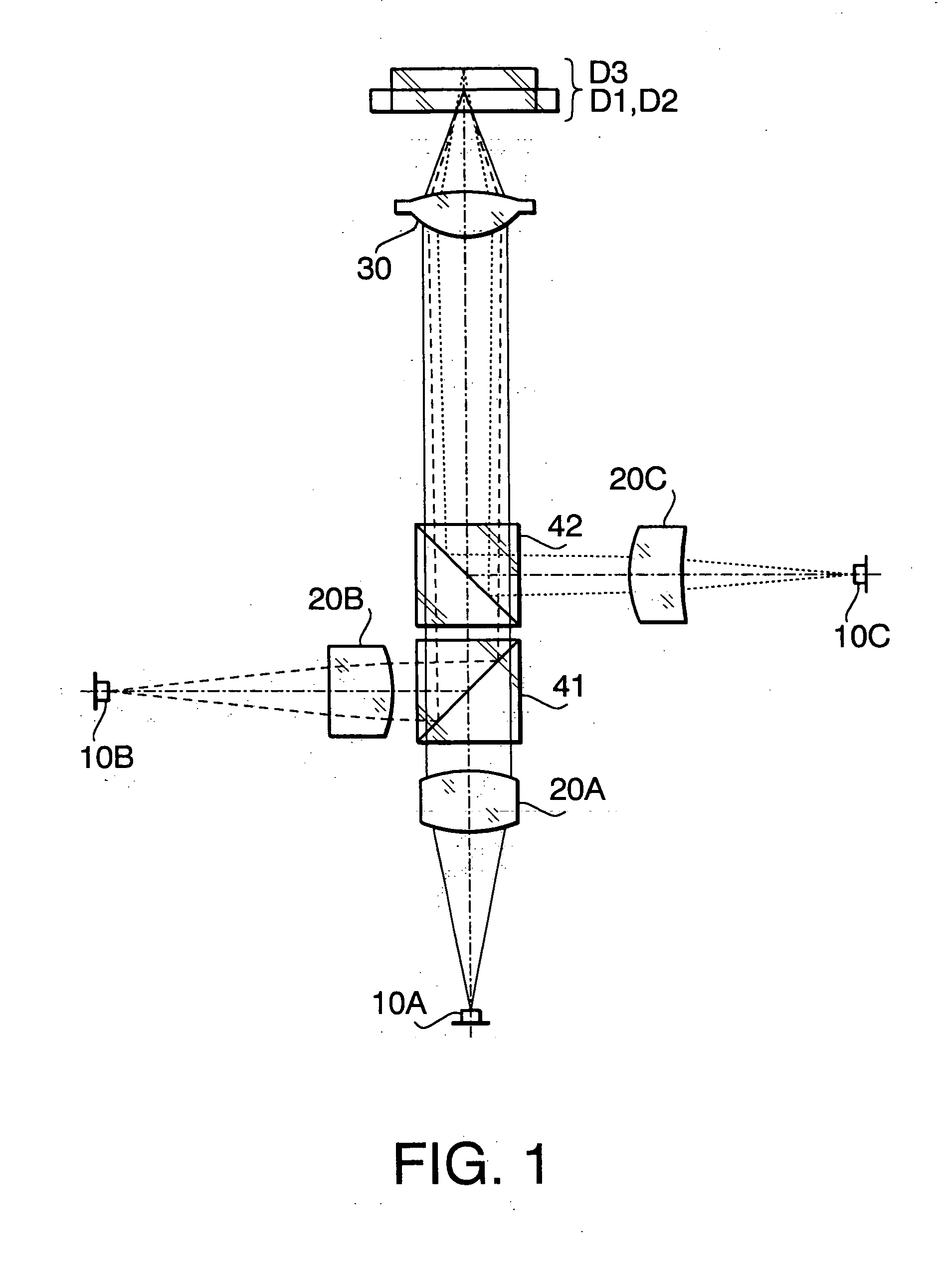
[0119] The optical pick-up 100 according to a first example has the configuration shown in FIGS. 1 and 2. In the first example, the objective lens 30 does not have the diffracting structure. Performance specifications of the objective lens 30 according to the first example are shown in Table 1.

TABLE 1First laserSecond laserThird laserbeambeambeamDesign405nm657nm788nmwavelengthf Focal2.850mm2.944mm2.961mmlengthNA0.7000.6500.500magnification0.000−0.024−0.083

[0120] In Table 1 (and in the following similar Tables), a design wavelength means a wavelength suitable for the recordation / reproduction of the optical disc, f represents a focal length (unit: mm) of the objective lens 30, NA represents the numerical aperture on the object side. In Table 1, the performance specifications are indicated with regard to each of the first laser beam (the optical disc D1), the second laser beam (the optical disc D2) and the third laser beam (the optical disc D3).

[0121] Table 2 shows a numerical confi...

second example

[0137] The optical pick-up 100 according to a second example has the configuration shown in FIGS. 1 and 2. In the second example, the diffracting structure is formed in the first, second and third regions 31-33 on the first surface 30a of the objective lens 30. Performance specifications of the objective lens 30 according to the second example are shown in Table 8.

TABLE 8First laserSecond laserThird laserbeambeambeamDesign405nm657nm785nmwavelengthf Focal2.999mm3.104mm3.126mmlengthNA0.6500.6010.500magnification0.000−0.014−0.083

[0138] Table 9 shows a numerical configuration of the optical pick-up 100 when the optical disc D1 (the first laser beam) is used, Table 10 shows a numerical configuration of the optical pick-up 100 when the optical disc D2 (the second laser beam) is used, and Table 11 shows a numerical configuration of the optical pick-up 100 when the optical disc D3 (the third laser beam) is used.

TABLE 9SurfacennnNumberrd(405 nm)(657 nm)(785 nm)#017.10#1159.1201.501.56023...

third example

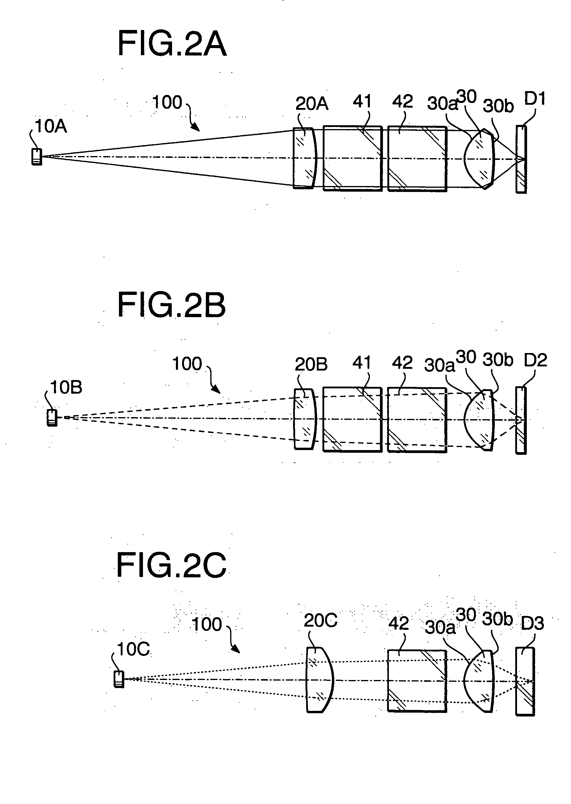
[0160] The optical pick-up 100 according to a third example has the configuration shown in FIG. 1. FIG. 10A is the configuration of the optical pick-up 100 when the optical disc D1 is used. FIG. 10B is the configuration of the optical pick-up 100 when the optical disc D2 is used. FIG. 10C is the configuration of the optical pick-up 100 when the optical disc D3 is used. In the third example, the diffracting structure is formed in the second region 32b on the first surface 30a of the objective lens 30. Performance specifications of the objective lens 30 according to the third example are shown in Table 17.

TABLE 17First laserSecond laserThird laserbeambeambeamDesign405nm657nm788nmwavelengthf Focal3.000mm3.100mm3.118mmlengthNA0.6500.6120.500magnification0.000−0.023−0.083

[0161] Table 18 shows a numerical configuration of the optical pick-up 100 when the optical disc D1 (the first laser beam) is used, Table 19 shows a numerical configuration of the optical pick-up 100 when the optical d...


PUM


Abstract

There is provided an objective lens for an optical pick-up which is used to record/reproduce data to/from at least three types of optical discs. Thicknesses t1, t2 and t3 of cover layers of first, second third optical discs are t1≅0.6 mm, t2≅0.6 mm, and t3≅1.2 mm. Numerical apertures NA1, NA2 and NA3 for the first, second and third optical discs satisfy a relationship NA1≧NA2>NA3. When the first optical disc is used, a substantially collimated light beam is incident on the objective lens. When the second or third optical disc is used, a diverging beam is incident on the objective lens. With regard to magnifications M1, M2 and M3 and focal lengths f1, f2 and f3 of the objective lens for the first, second and third optical discs, the following conditions (1), (2) and (3) are satisfied:
−0.02<fM1<0.02  (1)
−0.10<fM2<−0.04  (2)
−0.29<fM3<−0.19  (3).

Description

BACKGROUND OF THE INVENTION [0001] The present invention relates to an objective lens for an optical pick-up used for an optical disc drive, which is capable of recording data to and / or reproducing data from a plurality of types of optical discs having different recording densities and having different thicknesses of cover layers. [0002] There are various types of optical discs on which digital information is recorded at various densities, respectively. For example, a DVD (digital versatile disc) has a recording density higher that that of a CD (compact disc) or a CD-R (CD Recordable) and has a cover layer thinner than that of the CD or CD-R. [0003] When the recording / reproducing for the DVD having a higher recording density is performed, a smaller beam spot diameter is required on the data recording layer of the DVD relative to a beam spot used for the CD having a lower recording density. For this reason, the optical pick-up is configured such that a NA (numerical aperture) is chan...

Claims


Application Information

Patent Timeline
IPC IPC(8): G11B7/00G11B7/125G11B7/135
CPCG11B7/1275G11B7/1353G11B2007/0006G11B7/1374G11B7/1367
Inventor MARUYAMA, KOICHIKOREEDA, DAISUKE
Owner HOYA CORP
Why Eureka
Try Eureka