Objective lens, optical head and optical disk device
a technology applied in the field of optical head and optical disk device, can solve the problems of increasing light intensity loss and other problems, and achieve the effect of suppressing light intensity loss and improving diffraction efficiency
- Summary
- Abstract
- Description
- Claims
- Application Information
AI Technical Summary
Benefits of technology
Problems solved by technology
Method used
Image
Examples
first embodiment
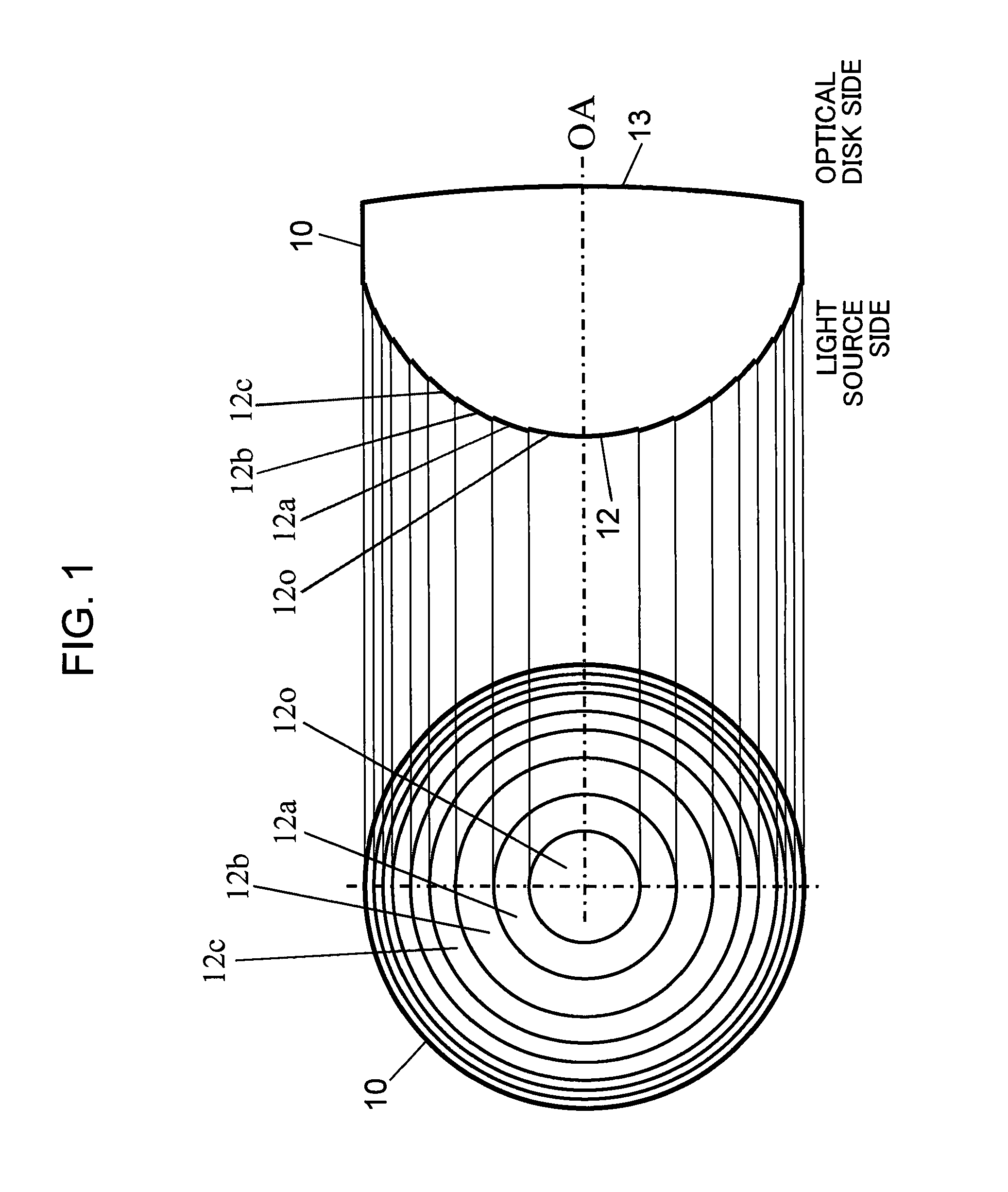
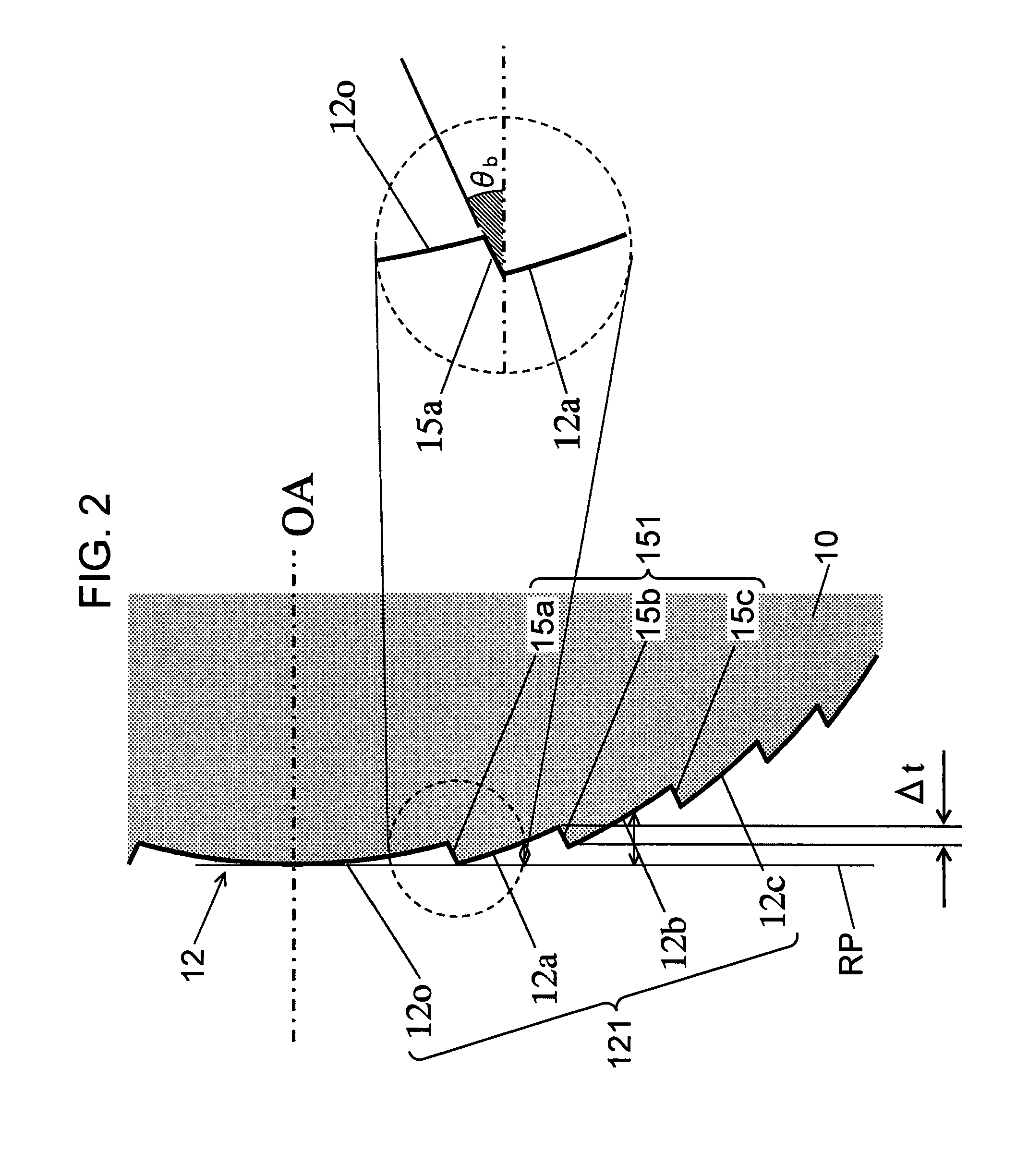
[0045]FIG. 1 is a diagram showing a configuration of an objective lens according to a first embodiment of the present invention. A left-hand side diagram in FIG. 1 is a plan view showing a configuration of a synthetic resin objective lens 10 according to the present first embodiment, and a right-hand side diagram in FIG. 1 is a sectional view showing a configuration of the objective lens 10. A lens surface 12 on a light source side (an incidence side of a laser beam) of the objective lens 10 comprises a spherical surface or an aspherical surface that constitutes a base. A sawtooth-shaped diffractive structure having a plurality of annular optical surfaces centered around an optical axis OA of the objective lens 10 is formed on the spherical surface or the aspherical surface that constitutes a base (hereinafter, collectively referred to as a base aspherical surface).
[0046]Meanwhile, a lens surface 13 on an optical disk side (an exit side of a laser beam) of the objective lens 10 whic...
second embodiment
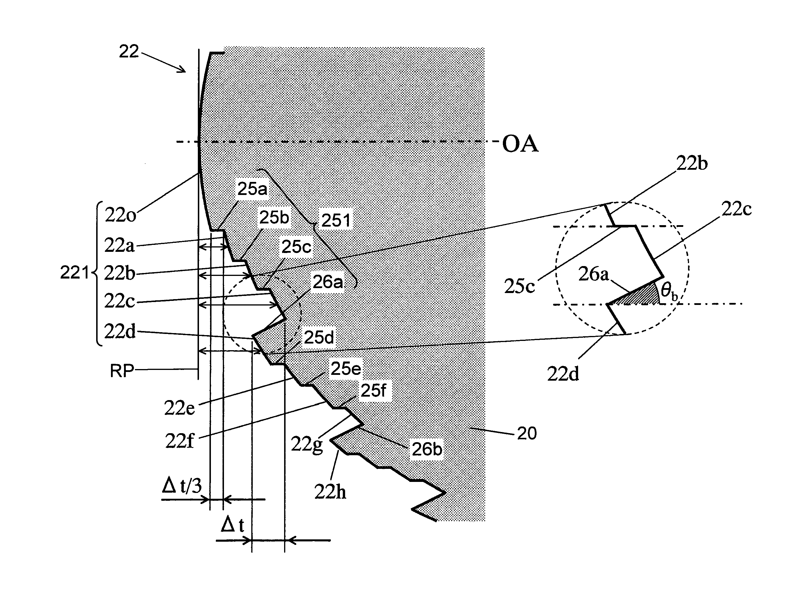
[0103]FIG. 7 is a diagram showing a configuration of an objective lens according to a second embodiment of the present invention. A left-hand side diagram in FIG. 7 is a plan view showing a configuration of a synthetic resin objective lens 20 according to the present second embodiment, and a right-hand side diagram in FIG. 7 is a sectional view showing a configuration of the objective lens 20. A lens surface 22 on a light source side (an incidence side of a laser beam) of the objective lens 20 comprises a base aspherical surface. A stair-shaped diffractive structure having a plurality of annular optical surfaces centered around an optical axis OA of the objective lens 20 is formed on the base aspherical surface.
[0104]Meanwhile, a lens surface 23 on an optical disk side (an exit side of a laser beam) of the objective lens 20 which opposes the lens surface 22 is configured as a spherical surface or an aspherical surface.
[0105]FIG. 8 is a partially enlarged sectional view showing a vic...
third embodiment
[0148]FIG. 12 is a diagram showing a configuration of an objective lens according to a third embodiment of the present invention. A left-hand side diagram in FIG. 12 is a plan view showing a configuration of a synthetic resin objective lens 30 according to the present third embodiment, and a right-hand side diagram in FIG. 12 is a sectional view showing a configuration of the objective lens 30 according to the present third embodiment. A lens surface 32 on a light source side (an incidence side of a laser beam) of the objective lens 30 comprises a base aspherical surface. A stair-shaped diffractive structure having a plurality of annular optical surfaces centered around an optical axis OA of the objective lens 30 is formed on the base aspherical surface.
[0149]Meanwhile, a lens surface 33 on an optical disk side (an exit side of a laser beam) of the objective lens 30 which opposes the lens surface 32 is configured as a spherical surface or an aspherical surface.
[0150]The lens surface...
PUM
| Property | Measurement | Unit |
|---|---|---|
| wavelength λ2 | aaaaa | aaaaa |
| thickness | aaaaa | aaaaa |
| thickness | aaaaa | aaaaa |
Abstract
Description
Claims
Application Information
 - R&D
- Intellectual Property
- Life Sciences
- Materials
- Tech Scout
- Unparalleled Data Quality
- Higher Quality Content
- 60% Fewer Hallucinations
Browse by: Latest US Patents, China's latest patents, Technical Efficacy Thesaurus, Application Domain, Technology Topic, Popular Technical Reports.
© 2025 PatSnap. All rights reserved.Legal|Privacy policy|Modern Slavery Act Transparency Statement|Sitemap|About US| Contact US: help@patsnap.com


