Hologram plate and its fabrication process

a technology of hologram plate and fabrication process, which is applied in the field of hologram plate and its fabrication process, can solve the problems of poor marring resistance of hologram photosensitive materials such as photopolymers, hologram on the hologram plate side is immediately damaged, and depositions are hardly removable, so as to reduce interface reflection, increase diffraction efficiency, and reduce the effect of interface reflection

Inactive Publication Date: 2005-05-12
DAI NIPPON PRINTING CO LTD
View PDF5 Cites 0 Cited by
  • Summary
  • Abstract
  • Description
  • Claims
  • Application Information

AI Technical Summary

Benefits of technology

[0031] Preferably in this case, the hologram layer is exposed to p-polarized lights P-polarized light is more reduced in interface reflection than s-polarized light, so that unnecessary interference fringes can be reduced during exposure and An (refractive index modulation) can be controlled to a reduced value as well.
[0032] However, when the diffraction efficiency of the CGH plate is too low as an example, the use of s-polarized light is preferable because An can be increased with an increased diffraction efficiency.
[0033] In the present invention for the purpose of achieving the aforesaid first object, the hologram plate comprises a multilayer structure made up of a first transparent substrate, a hologram layer, an adhesive layer and a second transparent layer and the second transparent substrate defines a surface in contact with a hologram photosensitive material during hologram replication, so that the second transparent substrate can function as a protective layer to make the hologram plate resistant to marring. In addition, the second transparent substrate can be used as a spacer for a double-focus replication process wherein the distance between the hologram plate and the hologram photosensitive material is set at substantially double the focal length of each collective element hologram, so that replicas can be fabricated with constant focal lengths.
[0034] An absorbing layer is located between the hologram layer and the adhesive layer or at other position to allow the zero-order light and first-order light diffracted by the hologram layer to have substantially the same intensity, so that hologram replicas of high diffraction efficiency can be obtained.
[0049] According to the present invention for achieving the aforesaid second object, all the unit holograms can be precisely replicated because the unit hologram segments are kept flush with one another by one common thin sheet glass provided over the plurality of juxtaposed unit hologram segments. When the hologram photosensitive material is brought into close contact with the multifaceted hologram plate with an index matching liquid applied therebetween for the purpose of hologram replication, it is extremely unlikely that an optical adhesive agent between adjacent unit hologram segments will be dissolved in the index matching liquid. If a glass sheet is used as the transparent thin sheet, improved durability is then obtained. Fabricated by the lamination of only unit hologram segments put in good alignment with good properties, the multifaceted hologram plate according to the present invention for achieving the aforesaid second object have all unit hologram segments of good quality and uniform properties, and so can be used for hologram replication with high efficiency.
[0054] Thus, the hologram plate for achieving the aforesaid third object of the present invention comprises a hologram layer with interference fringes formed thereon, a first layer capable of being removed with water or a solvent, which is provided on the surface of said hologram layer or a transparent layer formed thereon, and a second layer of a curing resin capable of being cured by light or heat, which is formed on said first layer. The second layer functions as a protective layer for the hologram layer 202, thereby preventing the marring, wearing and contamination of the hologram layer, which may otherwise occur at steps of coating an index matching liquid, carrying out contact replication, removing the index matching liquid, removing foreign matters, and so on. As many holograms are replicated, the second layer, too, is subjected to marring, wearing and contamination. In this case or, for instance, when one fails to form the first layer or the second layer, the hologram plate is washed with water or boiled in boiling water, so that the protective layer can be easily removed. Then, if fresh first and second layers are provided on the hologram layer, the hologram plate can be regenerated.

Problems solved by technology

Incidentally, hologram photosensitive materials such as photopolymers are generally poor in marring resistance whether in an unrecorded state or in a state subjected to post-recording treatments.
When replication is carried out with a hologram plate in close contact with a hologram photosensitive material, it is likely that the hologram on the hologram plate side is immediately damaged and some of the photosensitive material on the replication side peels off, depositing onto the hologram on the hologram plate side.
Such depositions are hardly removable.
However, this control is difficult on practical levels.
When a hologram plate having only one hologram (hologram color filter) equivalent to one segment is used for the replication of such a color filter as mentioned above, however, replication efficiency becomes worse.
However, when at least one of plural exposure operations (replication operations from the CGH plate) is improper, the resultant multifaceted hologram plate cannot be used or fails to provide a hologram plate having good replication efficiency.

Method used


Image

  • Hologram plate and its fabrication process
  • Hologram plate and its fabrication process
  • Hologram plate and its fabrication process

Examples


Embodiment Construction

[0070] Embodiments of the hologram plate according to the present invention and its fabrication process are now explained.

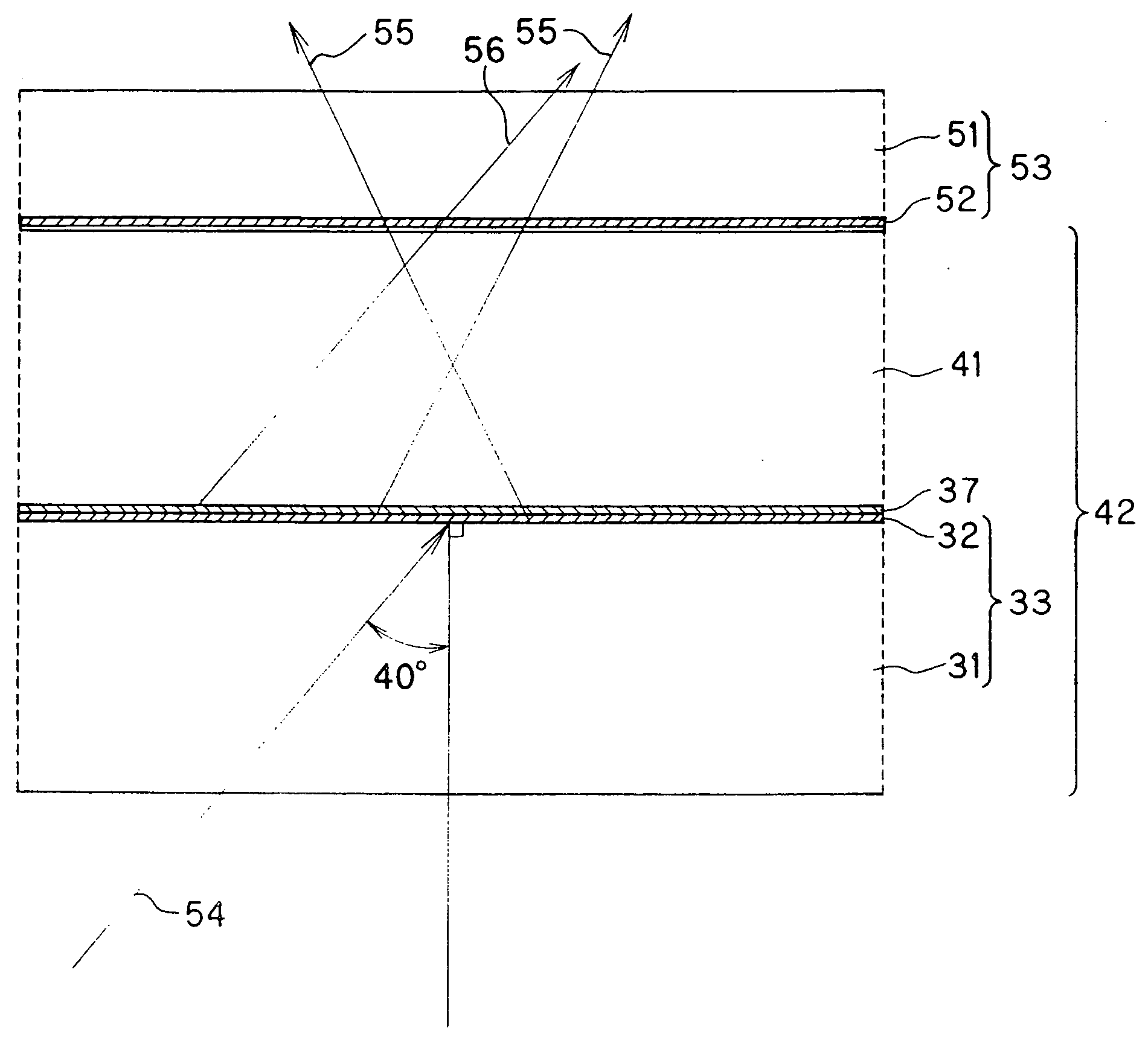
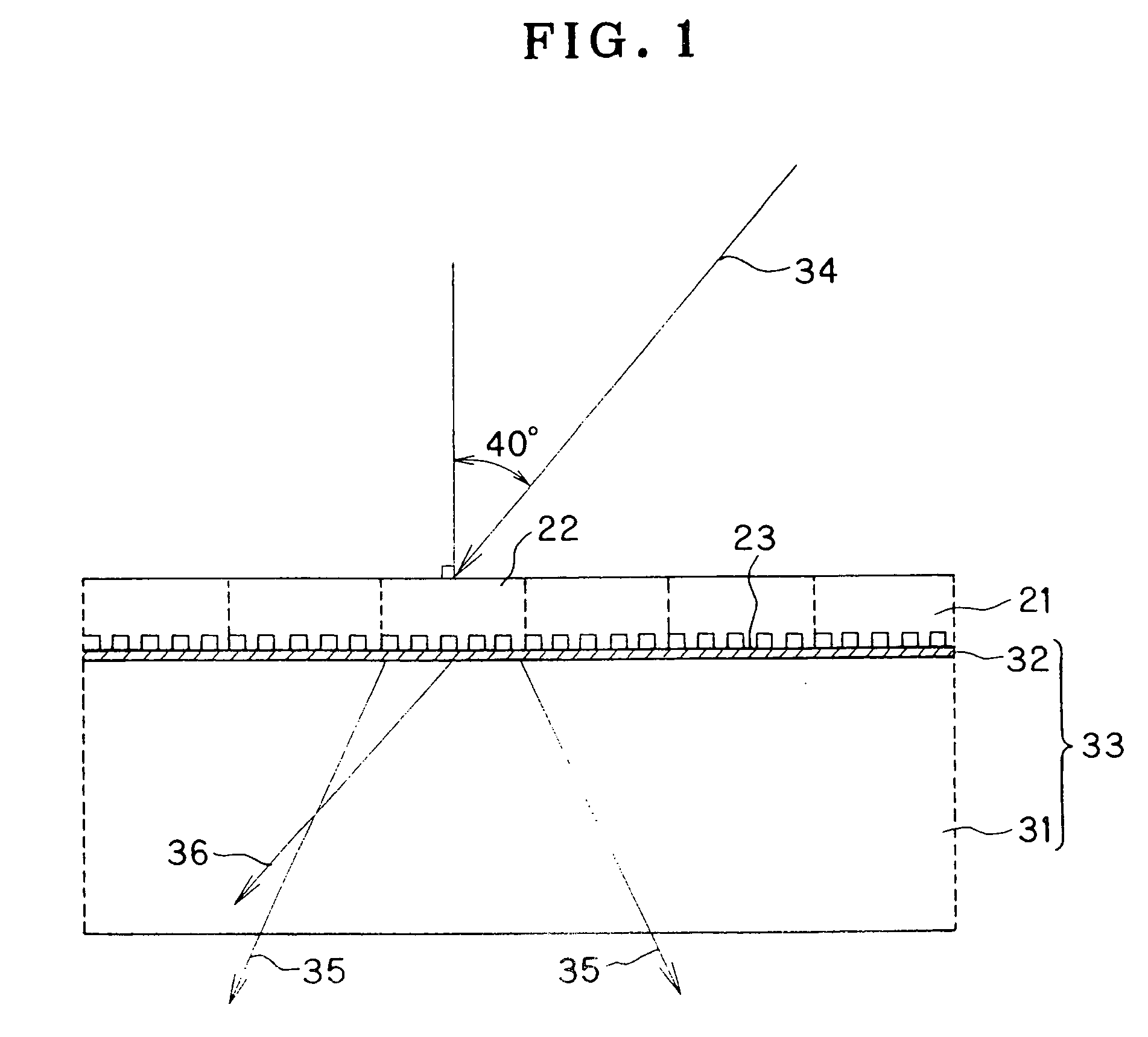
[0071] In the first embodiment of the present invention, the first hologram plate was fabricated in the form of a relief type computer-generated hologram (CGH) comprising an array of a transmission type of divergent element holograms. To fabricate this relief type CGH, the inference fringes of the divergent element holograms were first computed by means of a computer in such as a way that laser light of 488 nm wavelength, incident thereon at an incident angle of 40°, was diverged from a 50 μm focal length position on the incident side. Then, the interference fringes were rendered by means of electron beams on the surface of a glass substrate on which, for instance, an electron beam resist was coated, followed by development. In FIG. 1, the CGH array plate is shown at 21, the element holograms at 22, and a relief surface at 23.

[0072] On the other hand, a hologra...


PUM


Abstract

The invention provides a hologram plate which is used with the double-focus replication process, and which is integrated with a spacer to impart marring resistance thereto, and is integrated with a light absorbing layer to allow zero-order light and first-order light to have substantially the same intensity. This hologram plate 42 comprises an array of collective element holograms for diffracting parallel light incident thereon at a specific wavelength and a specific incident angle in such a way that the light is converged onto a specific focal length position. The hologram plate 42 is a multilayer structure made up of a first transparent substrate 31, a hologram layer 32, an adhesive layer 33 and a second transparent substrate 41. The second transparent substrate 42 defines a surface in contact with a hologram photosensitive material 53 during hologram replication.

Description

BACKGROUND OF THE INVENTION [0001] The present invention relates generally to a hologram plate and its fabrication process, and more specifically to a hologram plate designed to replicate a hologram array comprising collective element holograms such as hologram color filters, and its fabrication process. [0002] The present invention is also concerned with a multifaceted hologram plate and its fabrication process. [0003] Further, the present invention is directed to the construction of a protective film for a hologram plate. [0004] In JP-A 06-222361, etc., the applicant has already come up with a hologram-harnessing color filter for the purpose of greatly increasing the efficiency of utilization of liquid crystal display backlights, etc. This hologram color filter is basically made up of an array of a transmission type of collective element holograms capable of diffracting parallel light incident thereon at a specific wavelength and a specific angle of oblique incidence in such a way...

Claims


Application Information

Patent Timeline
Patent Type & Authority Applications(United States)
IPC IPC(8): G03H1/20G03H1/30
CPCG02B5/203G02B5/32G03H1/0252G03H1/0256Y10S359/90G03H1/30G03H2001/306G03H2240/53G03H1/202
Inventor SEKINE, KEIKOKISHIMOTO, HIROSHIKATSUMATA, MASAKIHIGUCHI, YOICHIICHIKAWA, NOBUHIKOONUMA, TADATSUGU
Owner DAI NIPPON PRINTING CO LTD
Why Eureka
Try Eureka