Image forming apparatus
- Summary
- Abstract
- Description
- Claims
- Application Information
AI Technical Summary
Benefits of technology
Problems solved by technology
Method used
Image

Examples
first embodiment
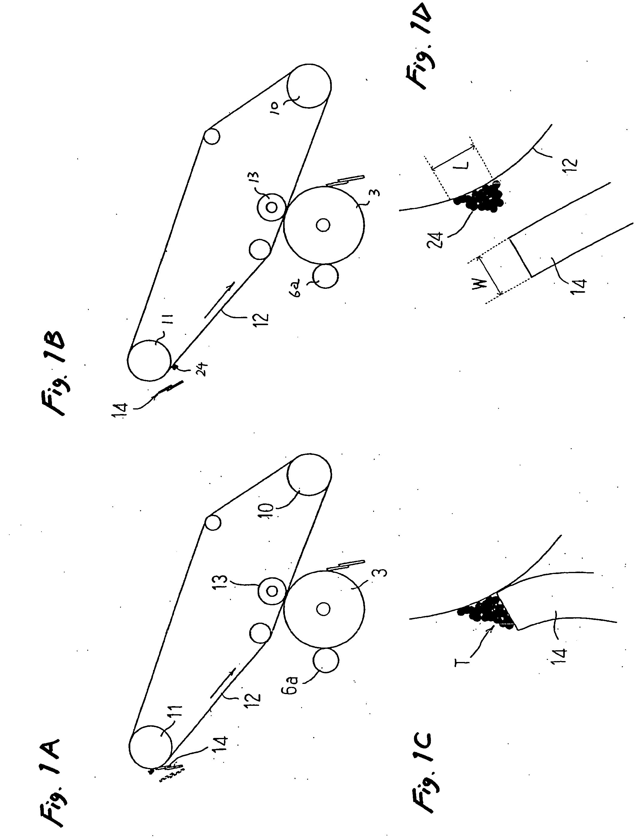
[0095] A control sequence according to the invention will be described with reference to FIGS. 12 to 14.
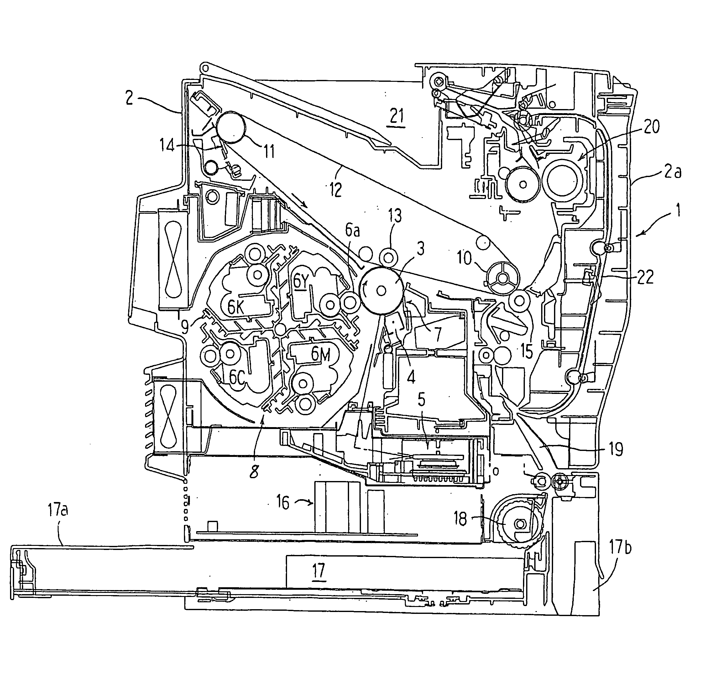
[0096] The surface of the image carrier 3 is uniformly charged by the charger 4, the image signal is turned on synchronously with the vertical synchronizing (vsync) signal, selective exposure according to image information of a first color is performed on the surface of the image carrier 3 to form an electrostatic latent image. At this time, the rotary developing unit 8 rotates so that the developing roller 6a for the first color comes into contact with the image carrier 3, a toner image of the first color is formed on the image carrier 3 and transferred to the intermediate transfer member 12 by the primary transfer roller 13 on which a primary transfer voltage is applied.
[0097] Incidentally, the belt cleaner 14 and the secondary transfer roller 15 are separated from the intermediate transfer member 12. The image of four full colors is formed by the toner images according to the ...
second embodiment
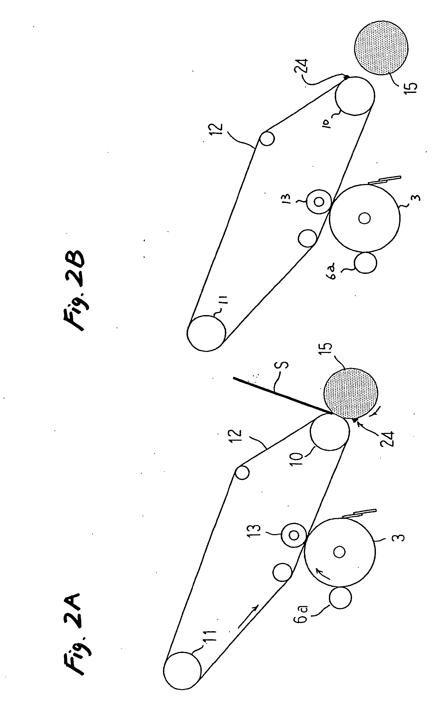
[0099] A control sequence according to the invention will be described with reference to FIGS. 15 to 17.
[0100] As shown in FIG. 15, the surface of the image carrier 3 is uniformly charged by the charger 4, the image signal is turned on synchronously with the vsync signal, selective exposure according to image information of the first color is performed on the surface of the image carrier 3 to form an electrostatic latent image. Incidentally, the rotary developing unit 8 rotates so that the developing roller 6a for the first color comes into contact with the image carrier 3, and the toner image of the first color is formed on the image carrier 3.
[0101] When the developing roller 6a comes in contact with the position C2 on the image carrier 3 corresponding to the non-image area on the intermediate transfer member 12, the toner line 24 is attached to the image carrier 3 due to the impact of the developing roller 6a. However, in this embodiment, as shown in detail in FIG. 16, the image...
third embodiment
[0102] A control sequence according to the invention will be described with reference to FIGS. 18 to 20.
[0103] As shown in FIG. 18, the surface of the image carrier 3 is uniformly charged by the charger 4, the image signal is turned on synchronously with the vertical synchronizing (vsync) signal, selective exposure according to image information of a first color is performed on the surface of the image carrier 3 to form an electrostatic latent image. At this time, the rotary developing unit 8 rotates so that the developing roller 6a for the first color comes into contact with the image carrier 3, a toner image of the first color is formed on the image carrier 3 and transferred to the intermediate transfer member 12 by the primary transfer roller 13 on which a primary transfer voltage is applied.
[0104] Incidentally, the belt cleaner 14 and the secondary transfer roller 15 are separated from the intermediate transfer member 12. The image of four full colors is formed by the toner ima...
PUM
 Abstract
Description
Claims
Application Information
 - Generate Ideas
- Intellectual Property
- Life Sciences
- Materials
- Tech Scout
- Unparalleled Data Quality
- Higher Quality Content
- 60% Fewer Hallucinations
Browse by: Latest US Patents, China's latest patents, Technical Efficacy Thesaurus, Application Domain, Technology Topic, Popular Technical Reports.
© 2025 PatSnap. All rights reserved.Legal|Privacy policy|Modern Slavery Act Transparency Statement|Sitemap|About US| Contact US: help@patsnap.com