Intake valve for a high-pressure pump, in particular for internal combustion engine fuel

a high-pressure pump and high-pressure technology, which is applied in the direction of fuel injection pumps, liquid fuel engines, fuel injection apparatus, etc., can solve the problems of reducing the working life of the pump, affecting the working efficiency of the pump, so as to achieve high reliability and durable, easy pre-assemble

Inactive Publication Date: 2005-04-14
CT STUDI COMPONENTI PER VEICOL
View PDF7 Cites 10 Cited by
  • Summary
  • Abstract
  • Description
  • Claims
  • Application Information

AI Technical Summary

Benefits of technology

[0011] It is an object of the invention to provide a high-pressure pump intake valve enabling calibration of the opening pressure of the shutter, and which is easy to preassemble, is highly reliable and durable, and eliminates the aforementioned drawbacks typically associated with known intake-valves.

Problems solved by technology

The above known intake valve (valve 1) has various drawbacks, by resulting in unbalance of both the operating shaft and the delivery pressure of the cylinders when low flow, e.g. less than 30% of maximum flow, is demanded of the pump.
That is, the delay with which the various valves open varies, so that the pistons compress different amounts of fuel.
In very low flow conditions, as when the engine is run at idling speed, some of the valves may not even open at all, so that unbalance of the operating shaft of the pump is considerable and greatly reduces the working life of the pump.
Moreover, given its high elastic constant, the spring can only be calibrated within a tolerance range relatively wide.
In particular, the shutter spring has a high elastic constant and therefore requires a considerable pressure drop to open; on account of its location, the spring cannot be calibrated, so that numerous versions of the spring must be provided for different applications; the shape of the valve body makes automated preassembly of the valve difficult; and, finally, location of the intake conduit weakens the valve body, which, in use, is subject to cracking.

Method used


Image

  • Intake valve for a high-pressure pump, in particular for internal combustion engine fuel
  • Intake valve for a high-pressure pump, in particular for internal combustion engine fuel
  • Intake valve for a high-pressure pump, in particular for internal combustion engine fuel

Examples


Embodiment Construction

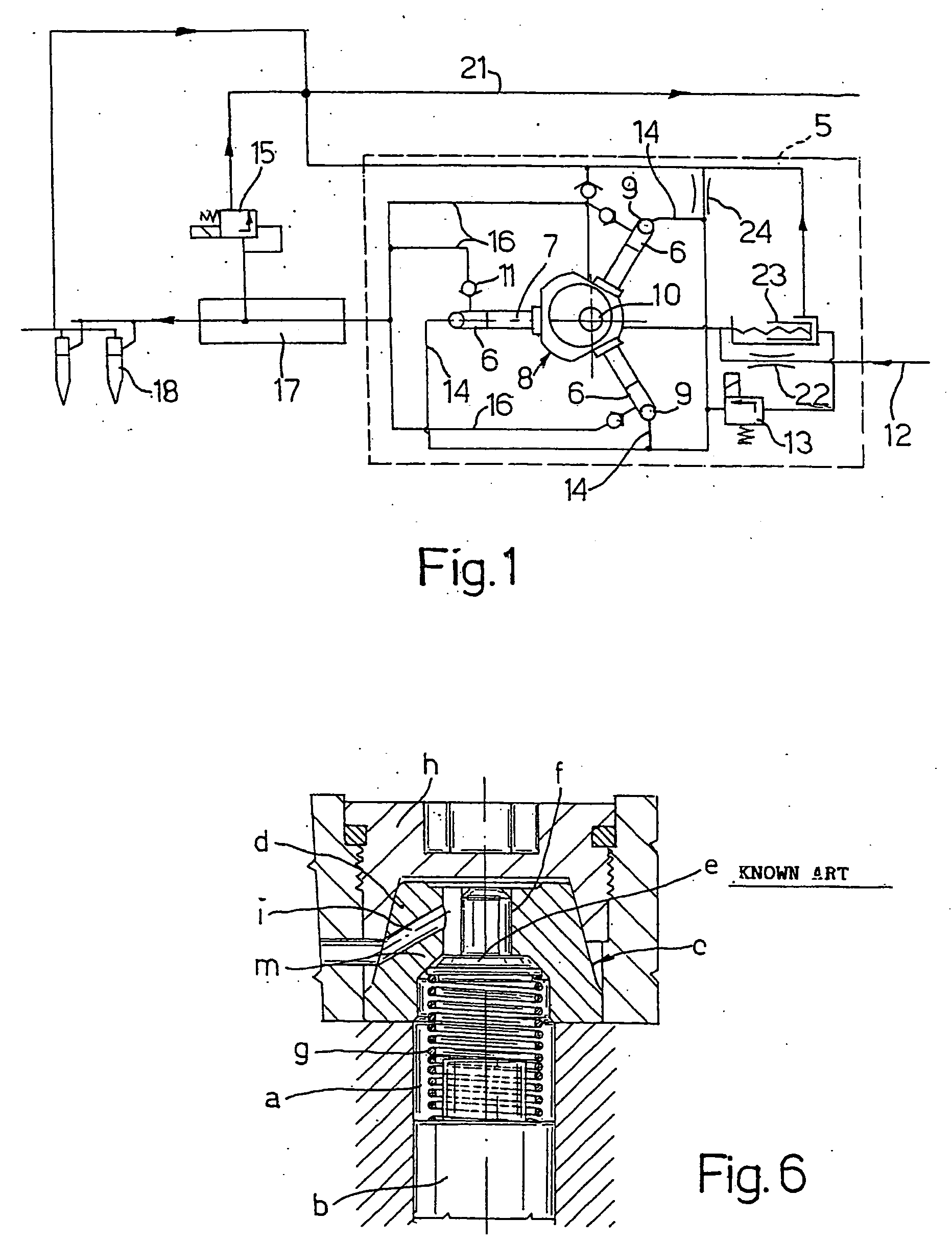
[0021] With reference to FIG. 6, a known high-pressure pump comprises a cylinder a in which slides a piston b; and an intake valve c (valve 2) carried by a valve body d having a truncated-cone-shaped lateral surface. Valve c is defined by a mushroom-shaped shutter comprising a plate e coaxial with cylinder a and guided inside a hole f in valve body d. A spring g is located between plate e and a shoulder of piston b, and acts variously on plate e during the stroke of piston b.

[0022] Spring g must provide a given opening pressure also at the bottom dead center position of piston b, and therefore has a high elastic constant. Valve body d is fixed to cylinder a by a threaded ring nut h having a cavity complementary in shape to that of body d, and has an intake conduit i which must leave the edge of ring nut h free. Intake conduit i therefore slopes, and forms in valve body d a weak region m which is easily cracked as a result of the impact of plate e.

[0023] With reference to FIG. 1, n...


PUM


Abstract

The valve (9) has a valve body (36) having a seat (42) with which cooperates a shutter (43) kept closed by a first spring (48) of substantially constant pressure, and by a second spring (49) varyuing in pressure during at least part of the stroke of the piston (7). The springs (48, 49) are helical compression types, and their pressures are summed on the shutter (43), which has a plate (44) and a stem (46). The first spring (48) is located between the valve body (36) and a flange (52) integral with a sleeve (53) which is fitted to the stem (46) in an adjustable position; and the second spring (49) is located between the plate (44) and the piston (7).

Description

TECHNICAL FIELD [0001] The present invention relates to an intake valve for a high-pressure pump, in particular for internal combustion engine fuel. BACKGROUND ART [0002] As is known, the fuel injected into internal combustion engine cylinders must be compressed to around 1600-bar pressure. Modern feed systems comprise a high-pressure piston pump for feeding the compressed fuel to a common rail communicating with the various engine injectors, and which in turn is supplied with fuel at around 5-bar pressure by a low-pressure pump. [0003] Each pump cylinder has an intake valve comprising a shutter normally closed by a spring, and which opens the valve when the difference in the fuel supply pressure in the cylinder exceeds the force or pressure exerted by the spring on the shutter. [0004] The pump normally comprises a group of radial pistons, e.g. three pistons spaced 120° apart, which are activated by a common cam actuator fitted to a shaft; and each shutter spring is appropriately ca...

Claims


Application Information

Patent Timeline
Patent Type & Authority Applications(United States)
IPC IPC(8): F02M51/04F02M59/06F02M59/08F02M59/34F02M59/46F02M63/02F04B1/04F04B53/10
CPCF02M59/06F02M59/08F02M59/464F04B53/102F04B1/0452F04B1/0465F02M63/0225
Inventor OLIVIERI, DAVIDESCHWARZ, THOMASFICARELLA, GIUSEPPE
Owner CT STUDI COMPONENTI PER VEICOL
Why Eureka
Try Eureka