Heater with an atomizer nozzle

a technology of atomizer and nozzle, which is applied in the field of atomizers, can solve problems such as and achieve the effects of avoiding chemical decomposition processes in the fuel, reliably preventing vaporization of liquid fuel, and avoiding slowing down the starting process

Inactive Publication Date: 2005-04-14
WEBASTO AG
View PDF69 Cites 8 Cited by
  • Summary
  • Abstract
  • Description
  • Claims
  • Application Information

AI Technical Summary

Benefits of technology

[0027] The aforementioned emission reduction during a stop phase can be further increased by first opening the fuel supply during the stop phase and by it only being blocked after a predetermined amount of liquid fuel has been converted into the essentially gaseous state with the heating means. By blocking the fuel supply, further vaporization of the liquid fuel is reliably prevented. With the gas which has remained in the blocked fuel line, a pressure equalization volume is created which especially prevents the liquid fuel from being compressed by the blocking means in the fuel line as a result of a temperature-induced pressure rise. Moreover, with the gas volume which has remained in the fuel supply, the foundation for a speedy restart of the burner is created as a result of the prevaporization of the liquid fuel.
[0028] In the partial gasification of the fuel which is otherwise supplied in liquid form, the liquid fuel with the heating means per unit of time is supplied with so much energy that the energy density on the surface of the heating means remains under a predetermined critical limit (the Leidenfrost phenomenon of film boiling). In this way, the energy can be efficiently delivered into the fuel and chemical decomposition processes in the fuel can be avoided. Alternatively or in addition, the temperature of the heated fuel should be within a predetermined temperature interval. This temperature interval is dependent on the type of the fuel and for diesel is, for example, roughly 170° C. to 400° C. Chemical decomposition of the fuel can be avoided in this way.
[0029] To vaporize the liquid fuel, the heating means of the present invention can be preheated advantageously before feed of the liquid fuel during a time interval of roughly 2 to 10 seconds, especially from roughly 2 to 6 seconds, and most preferably roughly 5 seconds. This preheating time ensures that the heating means makes available the required amount of energy for prompt and comprehensive vaporization of a predetermined amount of liquid fuel.

Problems solved by technology

This causes a relatively long preheating phase which slows down the starting process.
However, with preheating, there is always the danger of gas bubble formation in the liquid fuel and thus a not inconsiderable disruption of combustion during the starting and operating phase of a burner.

Method used


Image

  • Heater with an atomizer nozzle
  • Heater with an atomizer nozzle
  • Heater with an atomizer nozzle

Examples


Embodiment Construction

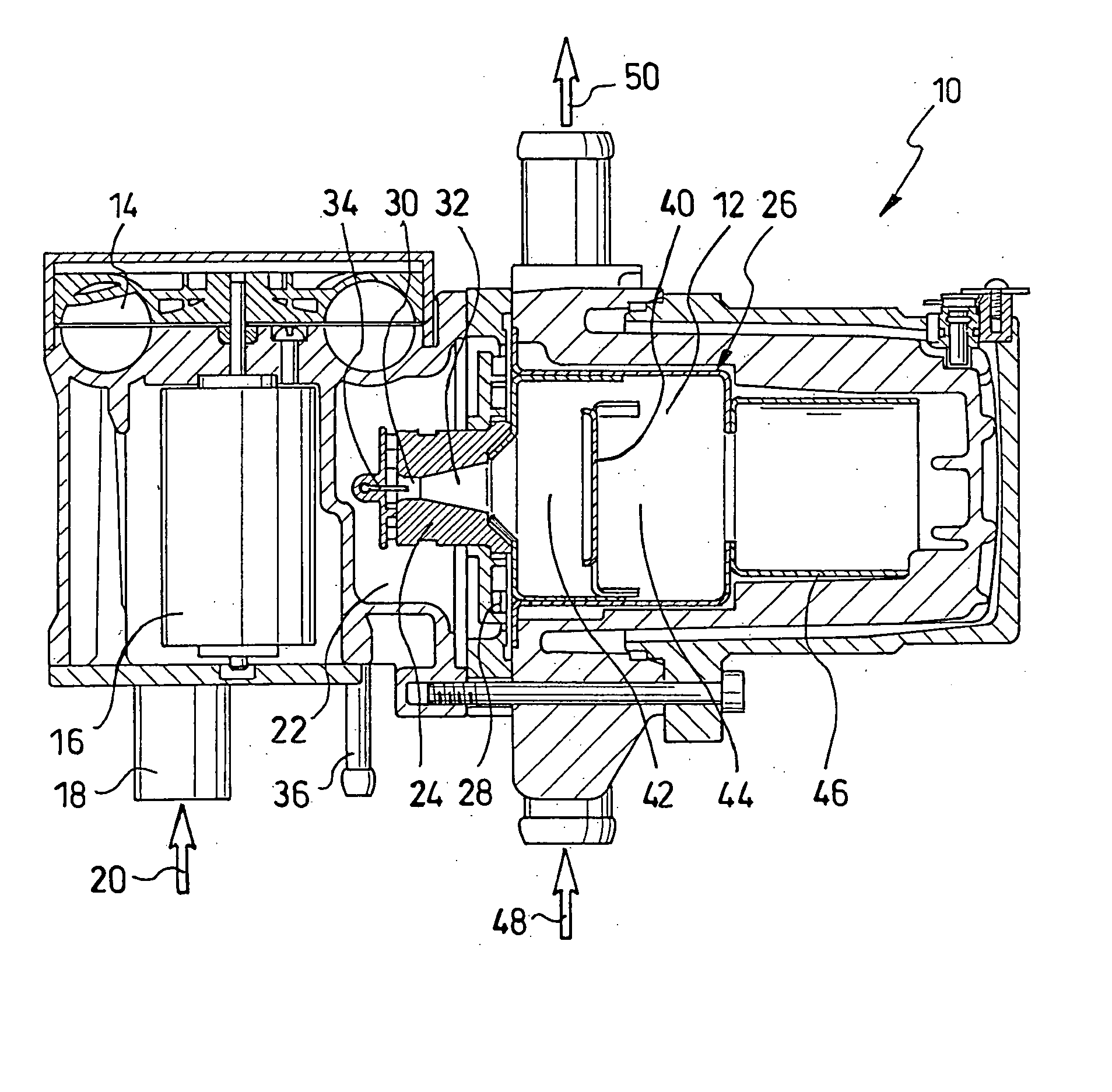
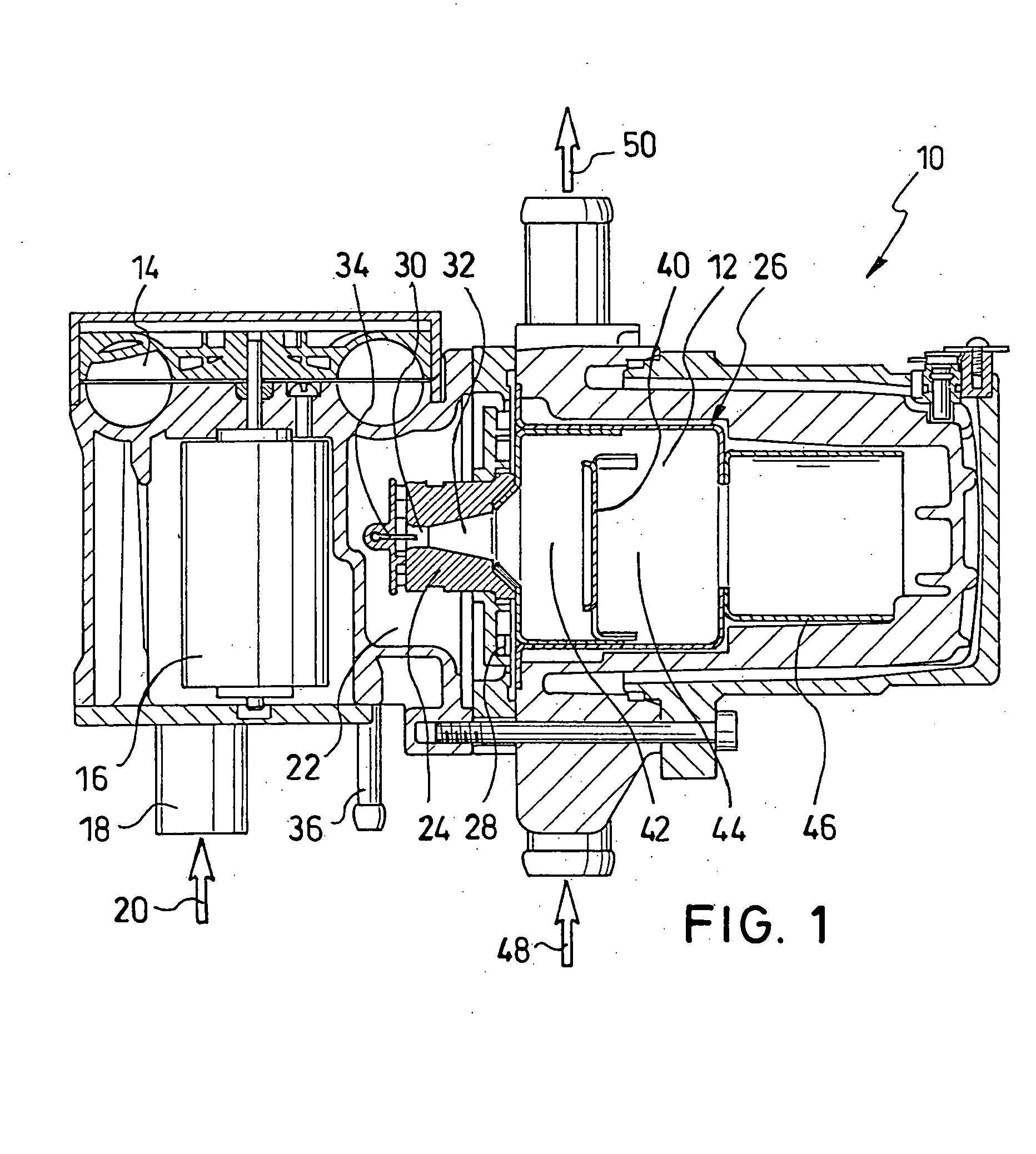
[0032]FIG. 1 shows a heater 10 which contains as the important component a burner 12 for burning a fuel / combustion air mixture. The heater 10 furthermore comprises an annular channel fan 14 with a fan motor 16 with which combustion air 20 is taken in via an air inlet connection 18 and is blown on the pressure side into the combustion air collecting space 22. Part of the combustion air which is made available in the combustion air collecting space 22 is delivered as primary air by an atomizer nozzle 24, which in this case is made as a Venturi nozzle, into the combustion chamber 26. The remaining part of the combustion air in the combustion air collecting space 22 is delivered as secondary air by secondary air holes 28 into the combustion chamber 26. Division of the combustion air into primary air and secondary air is useful in order to make available an ignitable mixture at the discharge of the atomizer nozzle 24 which is detailed below.

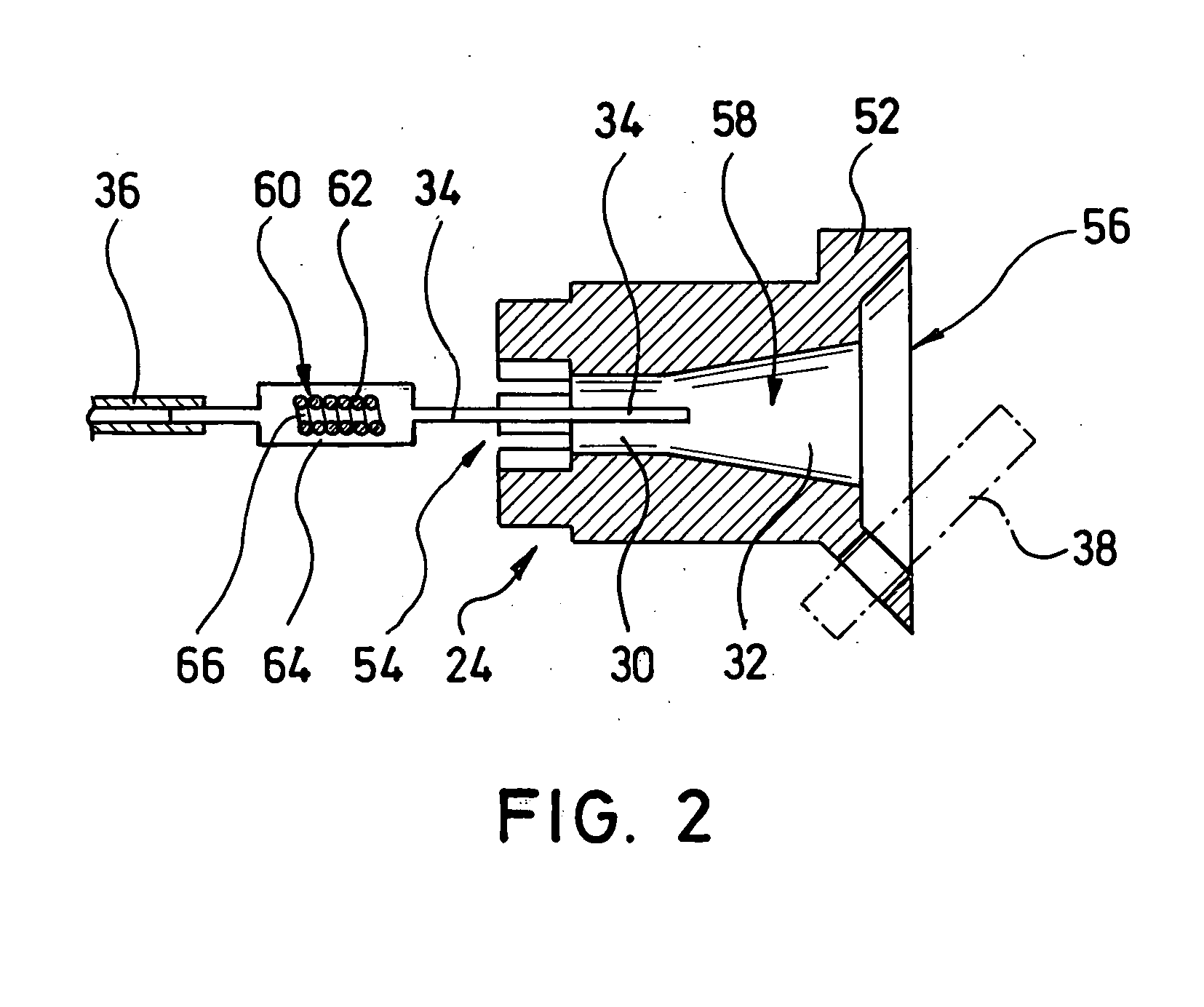
[0033] The atomizer nozzle 24 comprises an inl...


PUM


Abstract

A heater, especially for mobile applications, is provided which includes a burner for burning a liquid fuel, an atomizer nozzle located on the burner for atomizing the liquid fuel into extremely fine fuel droplets, and a fuel supply for feeding the liquid fuel to the atomizer nozzle. A heating means is provided on the atomizer nozzle with which the liquid fuel can be vaporized before and/or during its emergence from the atomizer nozzle.

Description

BACKGROUND OF THE INVENTION [0001] 1. Field of the Invention [0002] The present invention relates to a heater, especially for mobile applications, with a burner for burning a fossil liquid fuel, an atomizer nozzle which is located on the burner for atomizing the liquid fuel into extremely fine fuel droplets, and a fuel supply for feeding the liquid fuel to the atomizer nozzle. Furthermore the invention relates to a motor vehicle with such a heater and a process for operating a heater in which a liquid fossil fuel is supplied to an atomizer nozzle using a fuel supply. [0003] 2. Description of Related Art [0004] In heaters for mobile applications, burners for burning liquid fossil fuels are used. These burners are differentiated with respect to the type of combustion into atomizer burners and vaporizer burners. The atomizer burners are divided into two groups, so-called low pressure and so-called high pressure atomizer burners. In high pressure atomizer burners, the liquid fuel is del...

Claims


Application Information

Patent Timeline
Patent Type & Authority Applications(United States)
IPC IPC(8): F23D11/06F23D11/44
CPCF23D11/06F23D2900/11101F23D11/448
Inventor WARONITZA, JOSEFKEPPLER, MICHAELNOTHEN, MICHAELSTEFFENS, JAN
Owner WEBASTO AG
Why Eureka
Try Eureka