Transmitting method and transmitter apparatus

a transmitter and transmitter technology, applied in the direction of transmission monitoring, baseband system details, modulation, etc., can solve the problems of manual time-consuming and manual time-consuming job of timing adjustment discussed abov

Inactive Publication Date: 2005-04-14
PANASONIC CORP
View PDF6 Cites 150 Cited by
  • Summary
  • Abstract
  • Description
  • Claims
  • Application Information

AI Technical Summary

Benefits of technology

[0012] The present invention aims to provide a transmitting method and a transmitter apparatus which can save manual adjustment, adjust automatically a delay amount of a delaying means so that a distortion component out-of-band of a transmission signal can be minimized, and produce a correct timing.

Problems solved by technology

However, the timing adjustment discussed above is manually done and is a time-consuming job.

Method used


Image

  • Transmitting method and transmitter apparatus
  • Transmitting method and transmitter apparatus
  • Transmitting method and transmitter apparatus

Examples


exemplary embodiment 1

[0029] Exemplary Embodiment 1

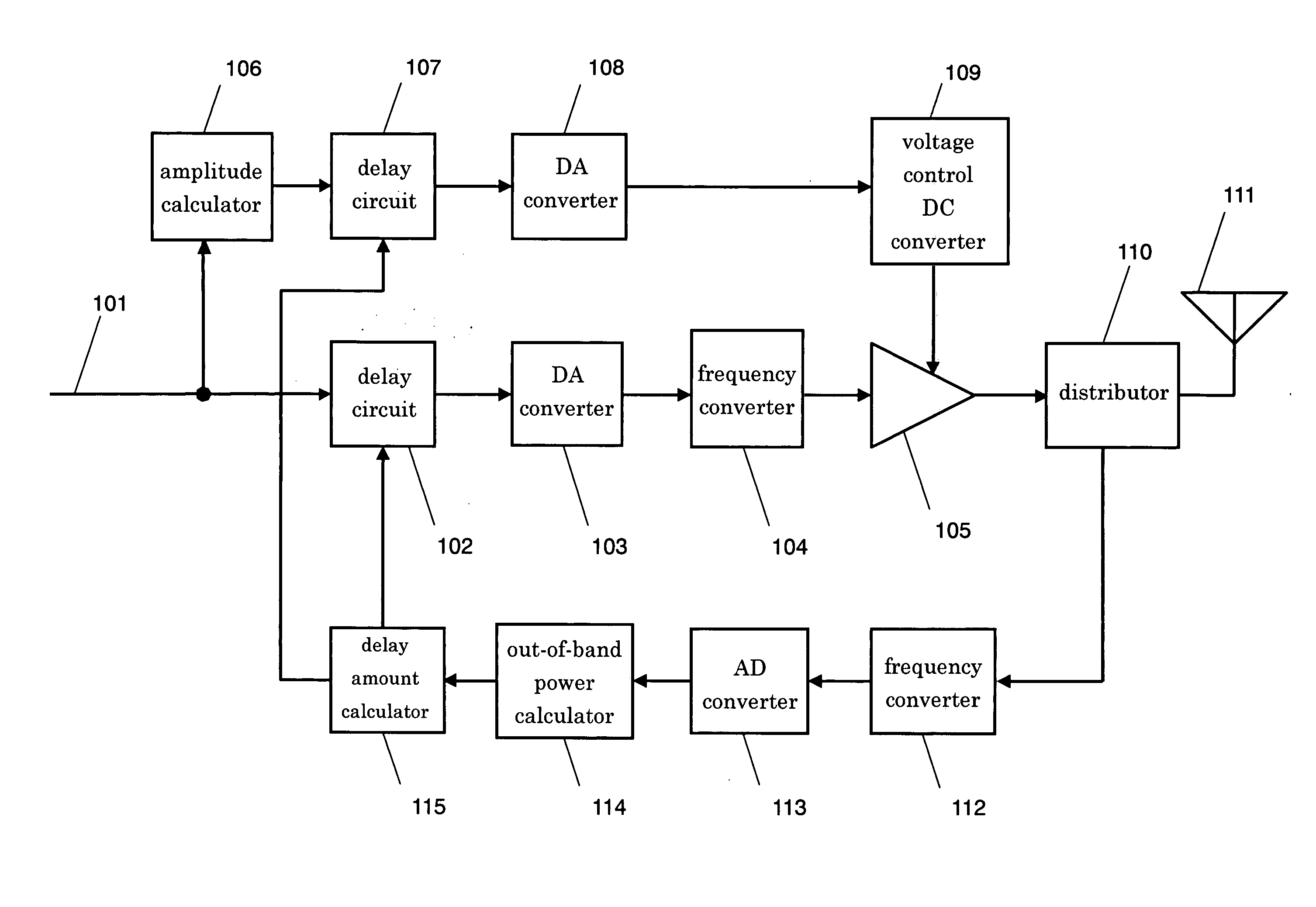
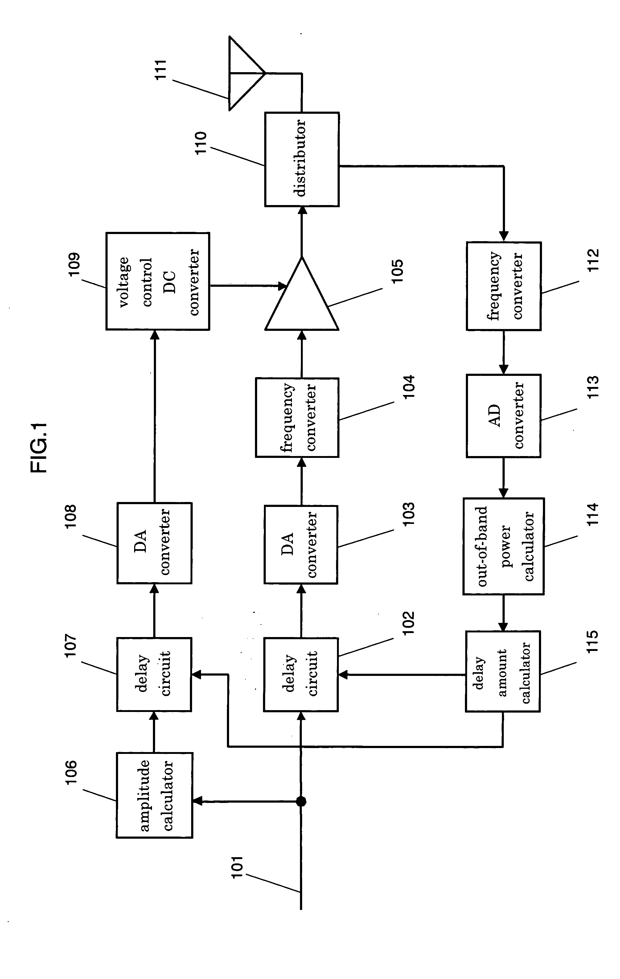
[0030]FIG. 1 shows a block diagram illustrating a transmitter apparatus in accordance with the first exemplary embodiment of the present invention. Delay circuit 102 delays its input signal before outputting it. DA converter 103 converts its input signal into an analog signal. Frequency converter 104 up-converts its input signal into an RF signal. Power amplifier 105 amplifies its input signal. Amplitude calculator 106 calculates an amplitude component of its input signal before outputting it.

[0031] Delay circuit 107 delays its input signal. DA converter 108 converts its input signal into an analog signal. Voltage control DC converter 109 outputs a voltage that controls power amplifier 105 based on an output from DA converter 108. Distributor 110 distributes an output from power amplifier 105 to antenna 111 and frequency converter 112.

[0032] Antenna 111 transmits the signal distributed by distributor 110. Frequency converter 112 converts a frequency of...

exemplary embodiment 2

[0041] Exemplary Embodiment 2

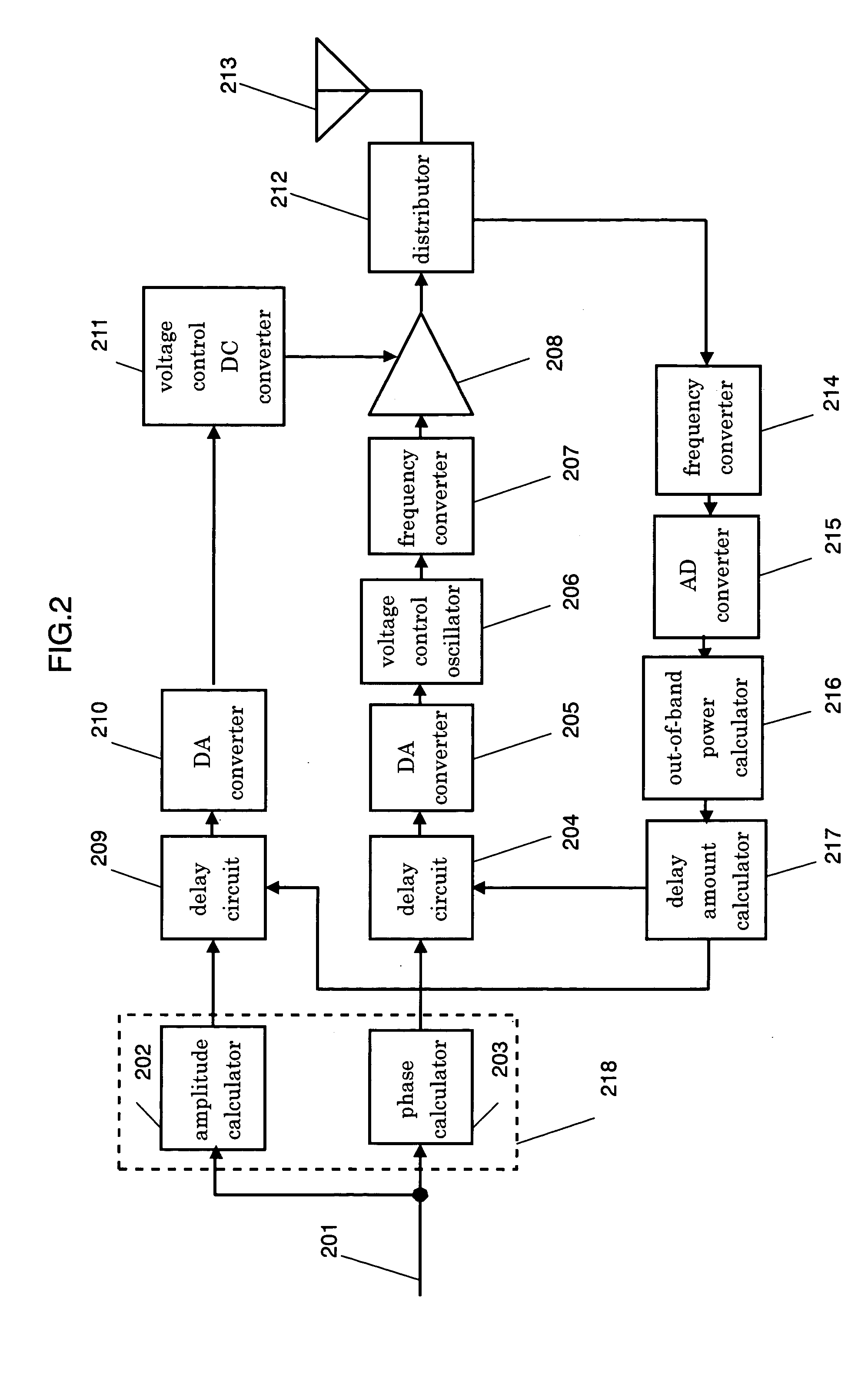
[0042]FIG. 2 shows a block diagram illustrating a transmitter apparatus in accordance with the second exemplary embodiment of the present invention. Computation circuit 218 is formed of amplitude calculator 202 and phase calculator 203. Amplitude calculator 202 calculates an amplitude component of transmission base-band signal 201 supplied thereto. Phase calculator 203 calculates a phase component of signal 201 supplied thereto. Delay circuit 204 delays an output signal supplied from phase calculator 203.

[0043] DA converter 205 converts the output from delay circuit 204 into an analog signal. Voltage control oscillator 206 carries out phase modulation based on the output from DA converter 205. Frequency converter 207 converts a frequency of the output from oscillator 206. Power amplifier 208 amplifies the output from frequency converter 207 up to a desirable level. Delay circuit 209 delays the output supplied from amplitude calculator 202.

[0044] DA con...

exemplary embodiment 3

[0053] Exemplary Embodiment 3

[0054]FIG. 3 shows a block diagram illustrating a transmitter apparatus in accordance with the third exemplary embodiment of the present invention. Computation circuit 518 is formed of amplitude calculator 502 and phase calculator 503. Amplitude calculator 502 calculates an amplitude component of transmission base-band signal 501 supplied thereto. Phase calculator 503 calculates a phase component of signal 501 supplied thereto. Delay circuit 504 delays an output signal supplied from phase calculator 503.

[0055] DA converter 505 converts the output from delay circuit 504 into an analog signal. Voltage control oscillator 506 carries out phase modulation based on the output from DA converter 505. Frequency converter 507 converts a frequency of the output from oscillator 506. Power amplifier 508 amplifies the output from frequency converter 507 up to a desirable level. Delay circuit 509 delays the output supplied from amplitude calculator 502.

[0056] DA conv...


PUM


Abstract

A transmitting method and a transmitter apparatus, which need no manual adjustment, are disclosed. A delay amount of a delay means is automatically adjusted such that an out-of-band distortion component of a transmission signal is minimized, and a correct timing is produced by the method and the apparatus. In this transmitter apparatus, a first delay means adjusts a control timing over a voltage that controls a power amplifying means, and a distributor distributes an output from the power amplifying means in order to feedback parts of the output. A distortion adjusting means calculates a distortion component of the transmission signal by using the signal fed back by the distributor, and adjusts automatically a delay amount of the first delay means so as to minimize the distortion component. This structure allows eliminating manual adjustment, and obtaining high power-efficiency with fewer distortions.

Description

TECHNICAL FIELD [0001] The present invention relates to a transmitting method and a transmitter apparatus that improve the linearity and the power efficiency of a power amplifier in a radio communication system. BACKGROUND ART [0002] A power amplifier of a transmitter apparatus in a radio communication system is a circuit that consumes the largest amount of power in the entire apparatus, thus the power amplifier has been required to improve its power efficiency. Radio communication systems in recent years transmit a large amount of data, so that linear modulation signals at a high speed and in a broadband are used. Thus a non-linear amplifier of high power-efficiency, such as class C or class D amplifier, is not used. Instead, a liner amplifier of lower power-efficiency, such as class A or class AB amplifier is used with an appropriate margin in back-off (difference between the max. output amplitude level and the saturated output power level). [0003] A smaller back-off for improving...

Claims


Application Information

Patent Timeline
Patent Type & Authority Applications(United States)
IPC IPC(8): H03F1/02H03F1/32H03G3/30H04B1/04
CPCH03F2200/102H03G3/3042H03G2201/103H03G2201/206H03G2201/307H04B1/0475H03F1/3282H04B2001/0433H03F1/0211H03F1/025H03F1/0255H03F1/32H03F1/3247H04B2001/0416H03F1/34H03F3/24
Inventor TAKABAYASHI, SHINICHIROUKENA, MASATOORIHASHI, MASAYUKIMATSUO, MICHIAKI
Owner PANASONIC CORP
Why Eureka
Try Eureka