Distortion compensation table creation method and distortion compensation method

a distortion compensation and table technology, applied in the direction of amplifier modifications to reduce non-linear distortion, digital transmission, baseband system details, etc., can solve the problems of large and complex circuit configuration, complex processing, and inability to execute at high speed, so as to reduce distortion components, simplify processing and speed up the effect of processing

Inactive Publication Date: 2006-04-20
PANASONIC CORP
View PDF7 Cites 7 Cited by
  • Summary
  • Abstract
  • Description
  • Claims
  • Application Information

AI Technical Summary

Benefits of technology

[0008] It is an object of the present invention to provide a distortion compensation table creation method and distortion compensation method that enable a small and simple circuit configuration to be used, enable processing to be simplified and speeded up, and also enable distortion components to be suppressed with high precision.

Problems solved by technology

However, a problem with a conventional distortion compensation table creation method and distortion compensation method is that DEMOD 113 and compensation data computation section 116 are necessary for compensation data table 104 generation, resulting in a large and complex circuit configuration.
A further problem with a conventional distortion compensation table creation method and distortion compensation method is that, since it is necessary to perform demodulation processing in DEMOD 113 and computational processing to find compensation data in compensation data computation section 116, processing is complex and cannot be executed at high speed.

Method used


Image

  • Distortion compensation table creation method and distortion compensation method
  • Distortion compensation table creation method and distortion compensation method
  • Distortion compensation table creation method and distortion compensation method

Examples


embodiment 1

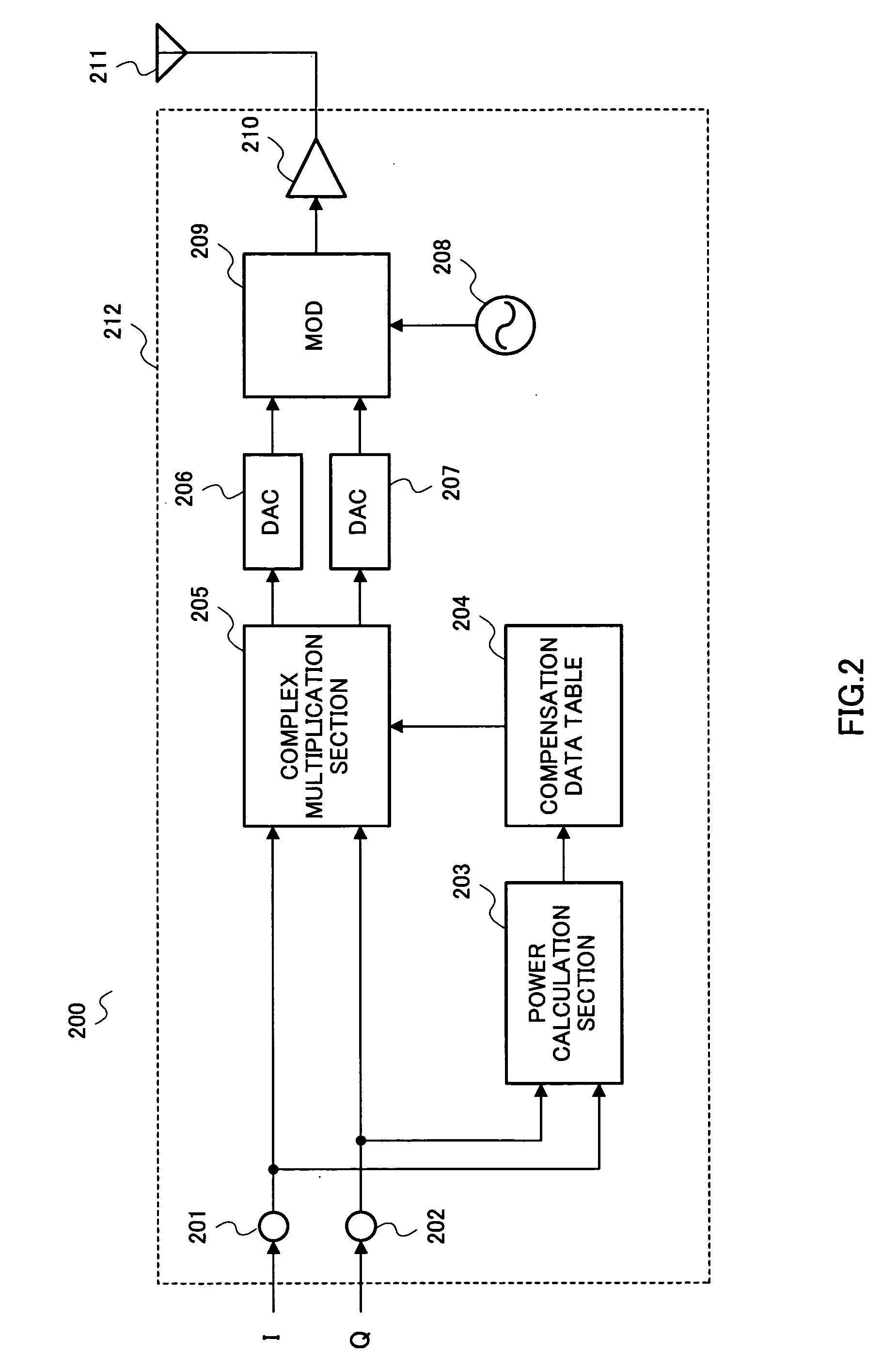
[0035]FIG. 2 is a block diagram showing the configuration of a transmitting apparatus 200 according to Embodiment 1 of the present invention. In FIG. 2, transmitting apparatus 200 is mainly composed of an input terminal 201, an input terminal 202, a power calculation section 203, a compensation data table 204, a complex multiplication section 205, a DAC 206, a DAC 207, an oscillator 208, a MOD 209, an amplifier 210, and an antenna 211.

[0036] Input terminals 201 and 202, power calculation section 203, compensation data table 204, complex multiplication section 205, DAC 206, DAC 207, oscillator 208, MOD 209, and amplifier 210 make up a distortion compensation apparatus 212. For distortion compensation apparatus 212 in FIG. 2, a predistortion distortion compensation apparatus configuration is shown, with power calculation section 203, compensation data table 204, and complex multiplication section 205 forming a predistortion function.

[0037] Input terminal 201 receives an I component ...

embodiment 2

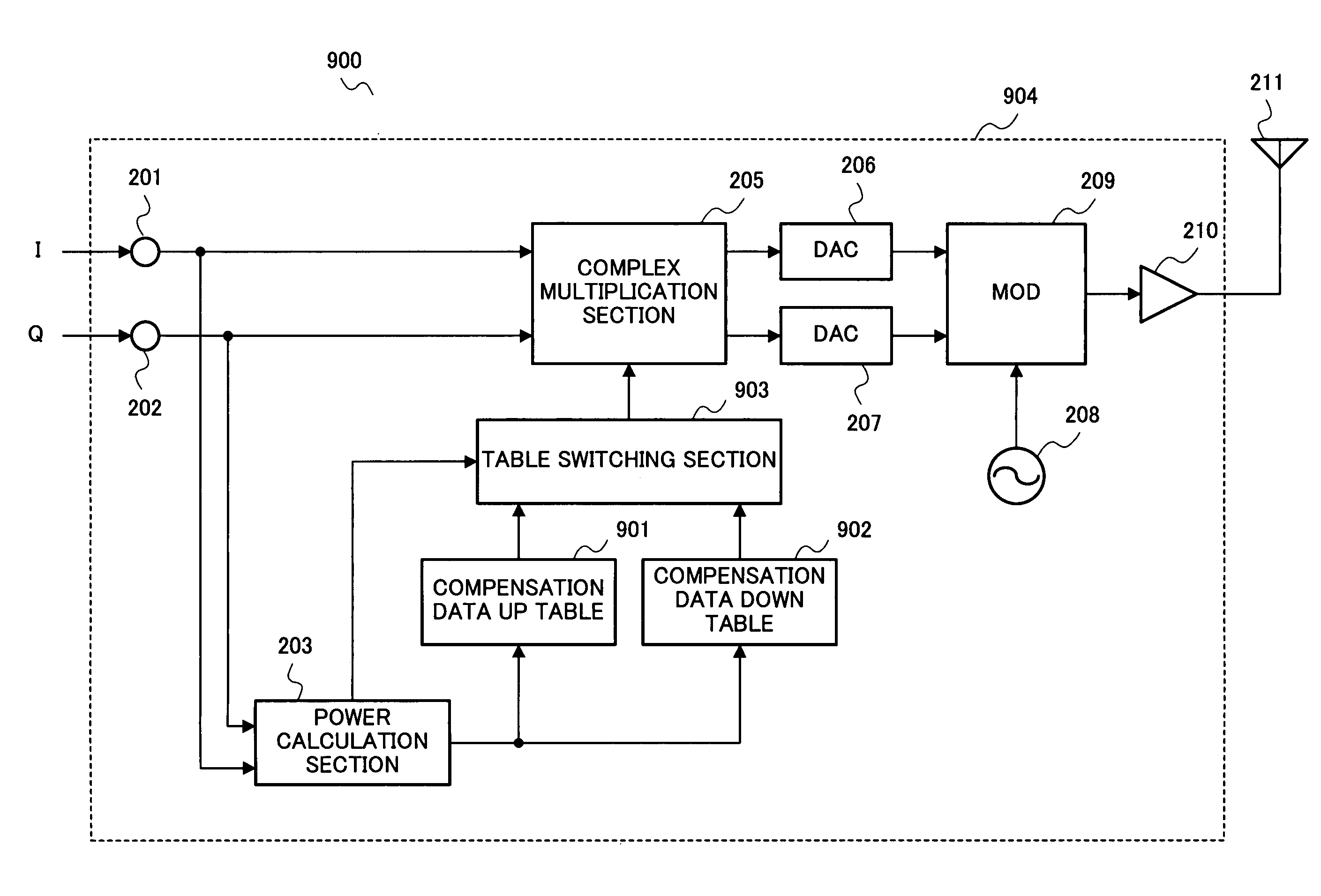
[0076]FIG. 9 is a block diagram showing the configuration of a transmitting apparatus 900 according to Embodiment 2 of the present invention.

[0077] As shown in FIG. 9, in transmitting apparatus 900 according to Embodiment 2, as compared with transmitting apparatus 200 according to Embodiment 1 shown in FIG. 2, a table switching section 903 is added, and a compensation data up table 901 and a compensation data down table 902 are provided instead of compensation data table 204. Parts in FIG. 9 identical to those in FIG. 2 are assigned the same codes as in FIG. 2, and descriptions thereof are omitted.

[0078] In FIG. 9, transmitting apparatus 900 is mainly composed of input terminal 201, input terminal 202, power calculation section 203, complex multiplication section 205, DAC 206, DAC 207, oscillator 208, MOD 209, amplifier 210, antenna 211, compensation data up table 901, compensation data down table 902, and table switching section 903.

[0079] Input terminals 201 and 202, power calc...

embodiment 3

[0102]FIG. 16 is a block diagram showing the configuration of a transmitting apparatus 1600 according to Embodiment 3 of the present invention.

[0103] As shown in FIG. 16, in transmitting apparatus 1600 according to Embodiment 3, as compared with transmitting apparatus 200 according to Embodiment 1 shown in FIG. 2, a compensation data table 1602 is provided instead of compensation data table 204, and determination section 1601 and an IM unbalance compensation computation section 1603 are added. Parts in FIG. 16 identical to those in FIG. 2 are assigned the same codes as in FIG. 2, and descriptions thereof are omitted.

[0104] In FIG. 16, transmitting apparatus 1600 is mainly composed of input terminal 201, input terminal 202, power calculation section 203, complex multiplication section 205, DAC 206, DAC 207, oscillator 208, MOD 209, amplifier 210, antenna 211, determination section 1601, compensation data table 1602, and IM unbalance compensation computation section 1603.

[0105] Inp...


PUM


Abstract

Fundamentals and IM waves comprising distortion signals are detected by vector measurement from an amplified baseband signal. Detected IM waves are related to power and frequency and plotted on the frequency axis. IM waves related to power and frequency are subjected to IFFT processing, and thereby converted so as to be related to time and power. Amplitude and phase components of IM waves subjected to IFFT processing are found. Compensation signal generation information is generated by relating a distortion compensation signal that has amplitude components of inverse amplitude to the amplitude components of IM waves and phase components of inverse phase to the phase components of IM waves to power, and creating a table by storing the generated compensation signal generation information in a compensation table. By this means, the circuit configuration can be made small and simple, processing can be simplified and speeded up, and distortion components can be suppressed with high precision.

Description

TECHNICAL FIELD [0001] The present invention relates to a distortion compensation table creation method and distortion compensation method, and, for example, to a distortion compensation table creation method and distortion compensation method that eliminate distortion generated when a signal is amplified. BACKGROUND ART [0002] Heretofore a predistortion distortion compensation apparatus has been known as an apparatus that compensates for distortion generated when a transmit signal is amplified in a radio communication apparatus. FIG. 1 is a block diagram showing the configuration of a conventional predistortion distortion compensation apparatus 100. [0003] Conventional predistortion distortion compensation apparatus 100 is composed of a baseband I input terminal 101, a baseband Q input terminal 102, a power calculation section 103, a compensation data table 104, a complex multiplication section 105, a digital / analog converter (hereinafter referred to as “DAC”) 106, a DAC 107, a mod...

Claims


Application Information

Patent Timeline
Patent Type & Authority Applications(United States)
IPC IPC(8): H04L25/49H03F1/32H04B1/04
CPCH03F1/3294H04B2001/0441H03F1/3223H03F3/24
Inventor NAGATA, HIDEOENOKI, TAKASHI
Owner PANASONIC CORP
Why Eureka
Try Eureka