Transmission Device

a technology of transmission device and terminal, which is applied in the direction of digital transmission, gated amplifier, baseband system details, etc., can solve the problems of poor operability and the surface area of the device to be enlarged, and achieve the effect of reducing the number of terminals for monitoring the input/output of the power amp

Active Publication Date: 2008-12-04
FUJITSU LTD
View PDF10 Cites 2 Cited by
  • Summary
  • Abstract
  • Description
  • Claims
  • Application Information

AI Technical Summary

Benefits of technology

[0020]It is accordingly one aspect of the present invention to provide a transmission device comprising an RF power amp, in which the number of terminals for monitoring the input / output of the power amp is reduced.
[0021]It is also an aspect of the present invention to provide a transmission device comprising an RF power amp, in which distortion components of an input monitor wave of the power amp when the power amp is switched OFF are decreased.
[0025]This enables the number of the monitor terminal to be confined to one and at the same time the monitor terminal is not required to be changed depending on ON / OFF state of the power amp, so that downsizing the RF base station and improving operability can be realized.
[0032]According to an aspect of the present invention, it is made possible to decrease the number of a monitor terminal of an RF power amp, and to monitor waveforms with less distortion components not only at the output but also the input of the power amp, depending on the power amp being made ON or OFF.

Problems solved by technology

While downsizing the radio base station is a big issue for recent customers' demands, the above prior art is disadvantageous in that it has two monitor terminals, i.e. an amp input monitor terminal and an amp output monitor terminal, causing the surface area of the device to be enlarged.
Therefore, each time the power amp is switched ON or OFF, the connections of the monitor terminals have to be changed, resulting in a poor operability.

Method used


Image

  • Transmission Device
  • Transmission Device
  • Transmission Device

Examples


embodiment

[3]

FIG. 7-9

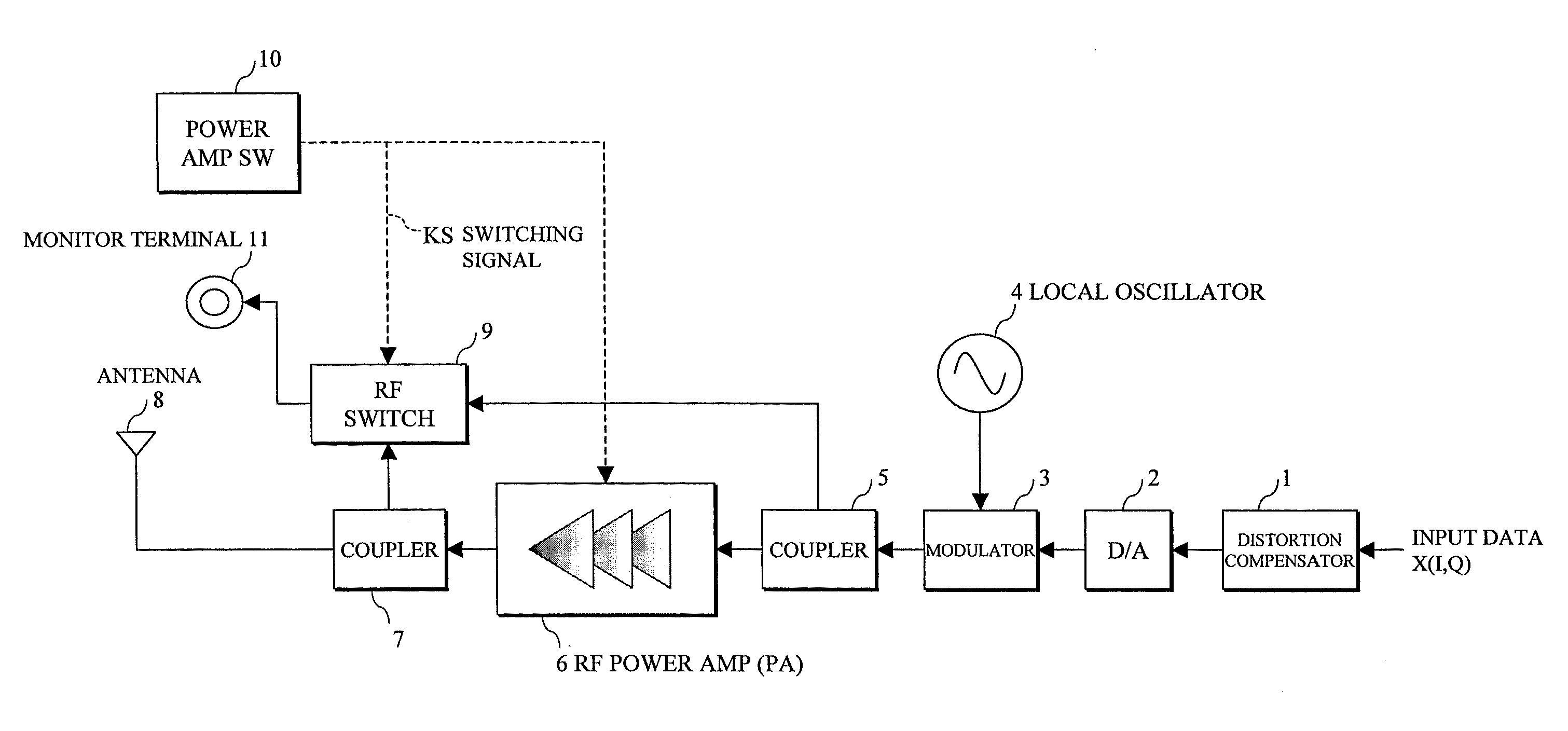
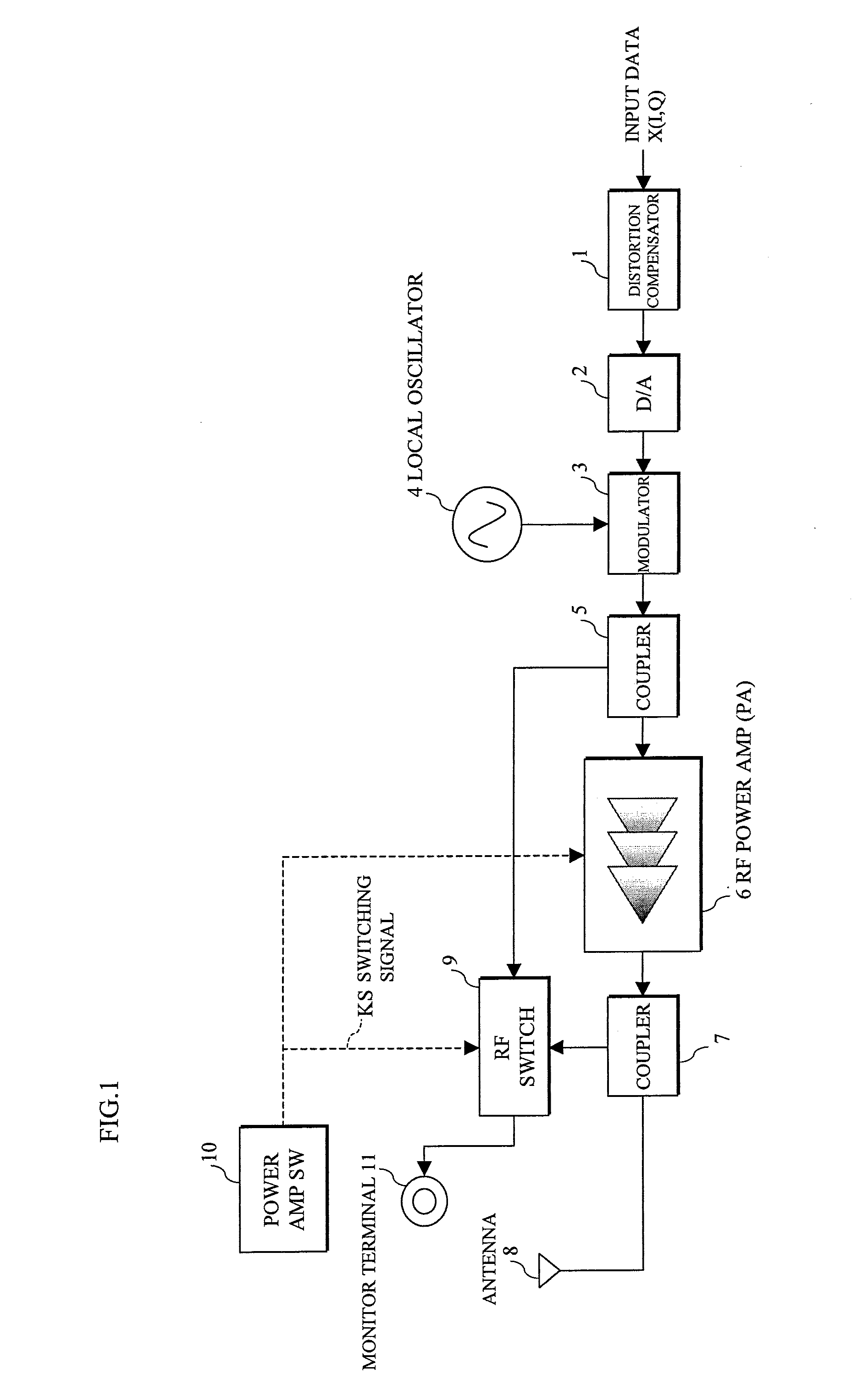
[0056]FIG. 7 shows an embodiment [3] of a transmission device. This embodiment [3] is different from the above embodiment [1] in that for outputting a modulated wave as it is with the distortion compensating function being suspended, the same feedback route as the prior art shown in FIG. 10 is provided, and a selector 18 is provided for validating / invalidating the distortion compensator 1 controlled by the feedback route in association with the switching signal KS from the power amp switch 10 being made ON or OFF. Therefore, this embodiment [3] only has to use a single coupler as an input signal detector.

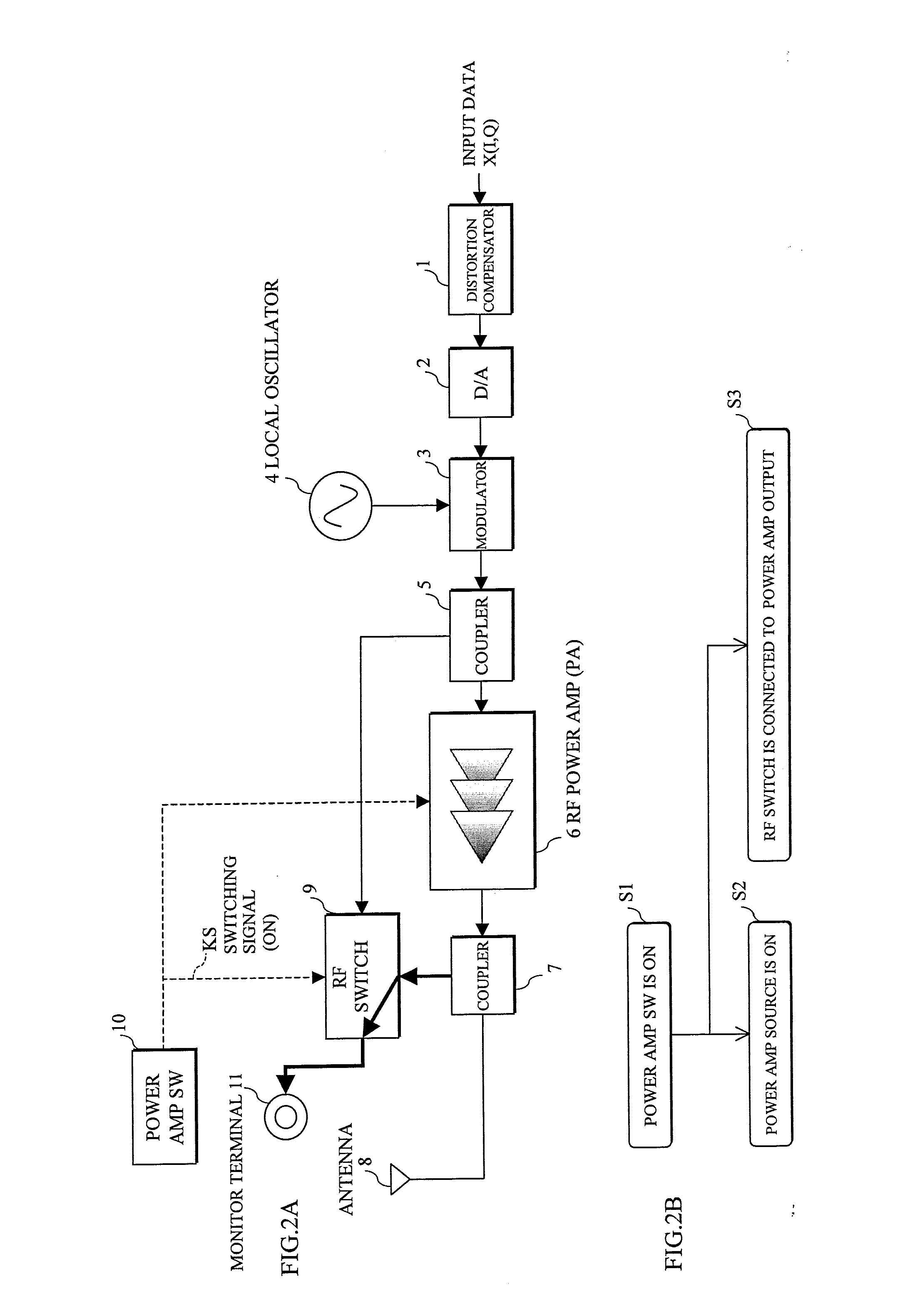
[0057]FIGS. 8 and 9 illustrate specific operations where the monitoring output of the RF power amp 6 is variously switched over in association with the power amp switch 10.

[0058]In an operation example where the switching signal KS from the power amp switch 10 is made ON as shown in FIG. 8A (step S61 in FIG. 8B), the RF power amp 6 is made ON (step S62), and the selector ...


PUM


Abstract

In a transmission device including an RF power amplifier with less number of terminals for monitoring an input / output signal of the RF power amplifier, there are provided with an input signal detector detecting the input signal; an output signal detector detecting the output signal; a first power amplifier switch switching ON or OFF the power amplifier; a monitor terminal; and an RF switch selecting an input signal or output signal of the power amplifier to be transmitted to the monitor terminal, in association with the first power amplifier switch being switched ON or OFF.

Description

CROSS-REFERENCE TO RELATED APPLICATIONS[0001]This application is related to and claims priority to Japanese Patent Application No. 2007-147205, filed on Jun. 1, 2007, in the Japan Patent Office, and incorporated by reference.BACKGROUND OF THE INVENTION[0002]1. Field of the Invention[0003]The present invention relates to a transmission device, and in particular to a transmission device, provided with a radio frequency or high frequency (hereinafter, represented by RF) power amplifier, applied to a radio base station.[0004]2. Description of the Related Art[0005]An RF power amplifier (hereinafter, abbreviated as amp) in a transmission device applied to a radio base station has the following functions:[0006]Function capable of switching ON or OFF a source of the power amp;[0007]Function capable of monitoring an input level of the power amp;[0008]Function capable of monitoring an output level of the power amp.[0009]A prior art arrangement of such a transmission device is shown in FIG. 10...

Claims


Application Information

Patent Timeline
Patent Type & Authority Applications(United States)
IPC IPC(8): H04B1/04
CPCH03F3/72
Inventor SHAKO, HIDEHARUOHBA, TAKESHINOHIRA, TOMOYOSHI
Owner FUJITSU LTD
Why Eureka
Try Eureka