Memory bus shared system
a memory bus and shared technology, applied in the direction of generating/distributing signals, digital transmission, instruments, etc., can solve the problem of affecting the efficiency of data transfer, and the size of dvd drivers is increased, so as to reduce the pin terminal number of the controller, increase the data transfer rate, and reduce the effect of bus utilization efficiency
- Summary
- Abstract
- Description
- Claims
- Application Information
AI Technical Summary
Benefits of technology
Problems solved by technology
Method used
Image
Examples
embodiment 1
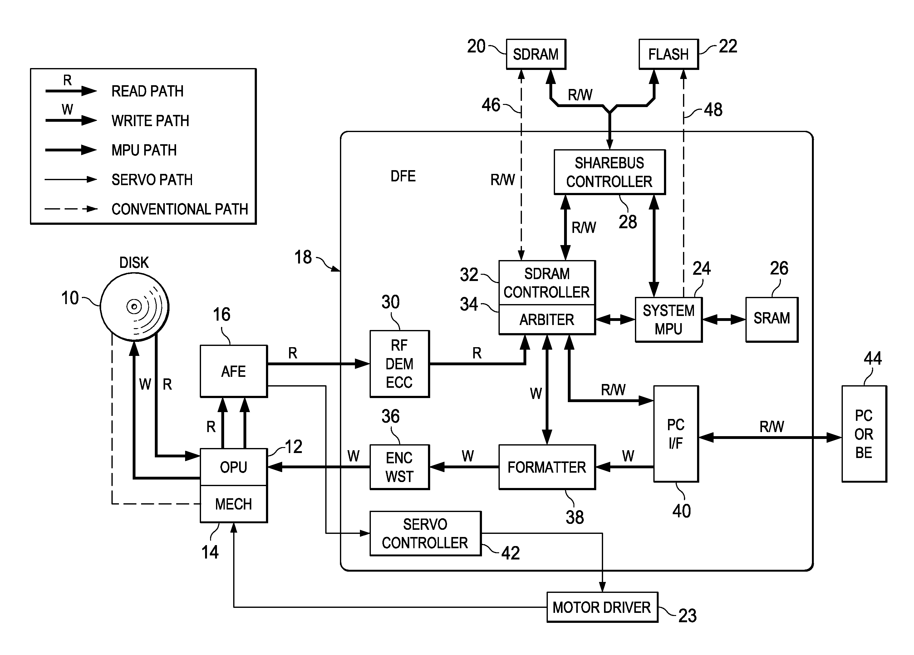
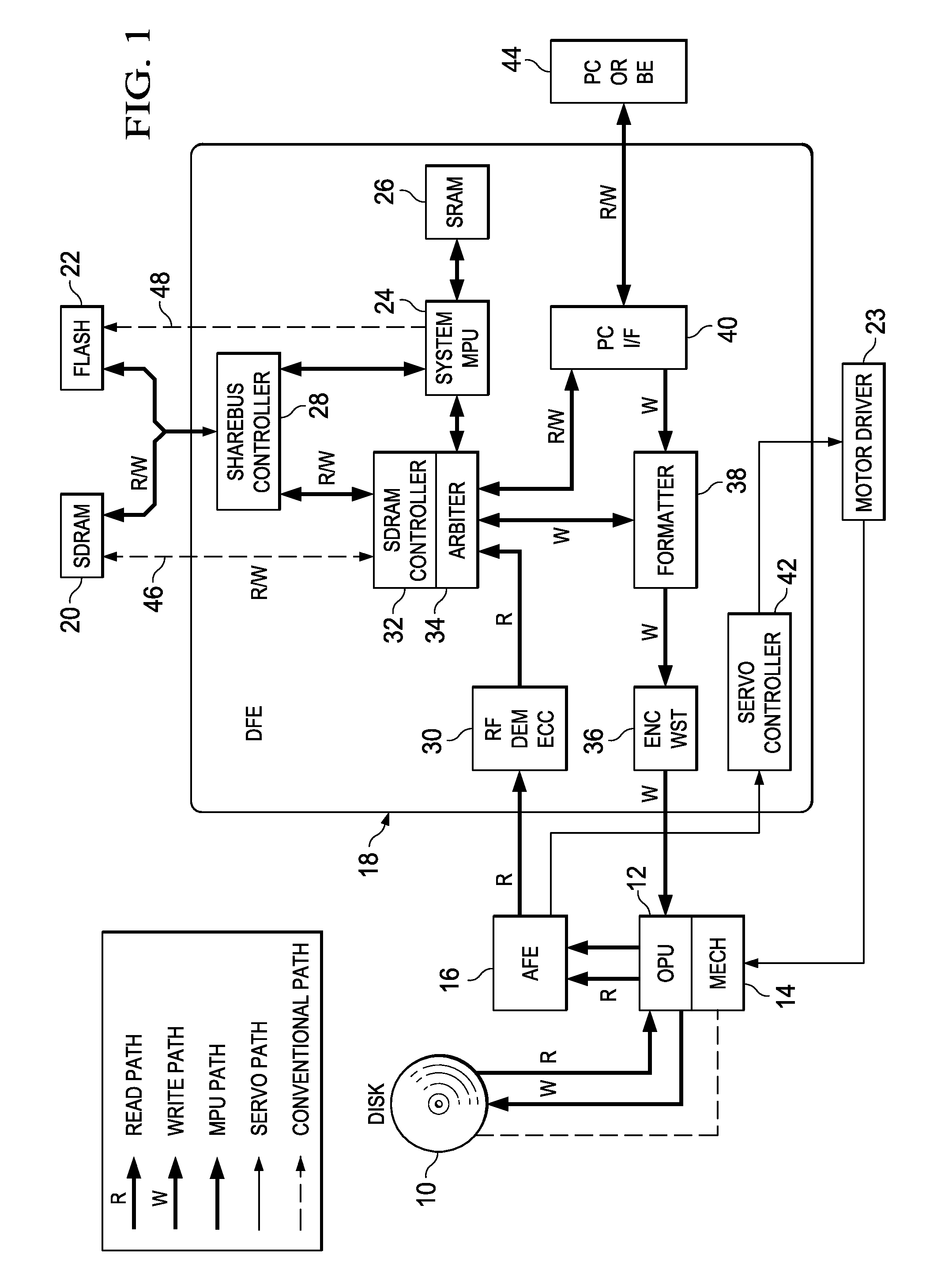
[0053]FIG. 4 is a diagram illustrating the state of connection between DFE 18 and SDRAM 20, FLASH 22 in the embodiment (Embodiment 1). FIG. 6 is a diagram illustrating the detailed pin configuration of said semiconductor packages 18, 20, 22 and an example of layout of the printed wiring. In FIG. 6, the printed board (not shown in the figure) having said semiconductor packages 18, 20, 22 assembled on it is made of a laminated wiring board containing wiring groups (50A), (50B), (50C), (50D) as a first layer of wiring, and wiring groups (52A), (52B), (52C) as a second layer of wiring.
[0054]As shown in FIG. 4, for DFE 18, MCLK represents a system clock output terminal, and MCKE represents a clock enable output terminal. They are respectively connected via individual control lines to clock input terminal CLK and clock enable input terminal CKE of SDRAM 20.
[0055]For DFE 18, MRAS represents a row address strobe output terminal, MCAS represents a column address strobe output terminal, and M...
embodiment 2
[0091]In Embodiment 2 shown in FIG. 12, the data of FLASH 22 have an 8-bit configuration, and the address has a 21-bit configuration. More specifically, data terminals D [15:0] of 16 bits of SDRAM 20 are connected to MD terminals [15:0] of 16 bits of DFE 18 via data bus D-Bus 1 with a width of 16 bits, and the 10-bit address terminals A [9:0] of SDRAM 20 are connected to 10-bit address terminals MA [9:0] of DFE 18 via 10-bit-width address bus A-Bus 1. Also, the 21-bit address terminals A [20:0] of FLASH 22 are connected via 10-bit address bus A-Bus 2 and 11-bit address bus A-Bus 3 to 10-bit address terminals CA [9:0] and 11-bit address terminals CA [20:10] of DFE 18. Here, In DFE 18, address terminals CA [9:0] and address terminals MA [9:0] are identical to each other. Also, the 8-bit data terminals DQ [7:0] of FLASH 22 are connected to 8-bit data terminals CD [7:0] of DFE 18 via 8-bit data bus D-Bus 2.
[0092]As explained above, in this Embodiment 2, a portion [9:0] of address termin...
embodiment 3
[0094]Also in said Embodiment 3, a portion [9:0] of address terminals A [19:0] of DFE 18 is connected commonly to address bus A-Bus 1 on the side of SDRAM 20 and address bus A-Bus 2 on the side FLASH 22. By means of this address bus sharing scheme, for SDRAM 20 with 35 pins and FLASH 22 with 32 pins, DFE 18 has 64 pins for allotting to two memories 20, 22.
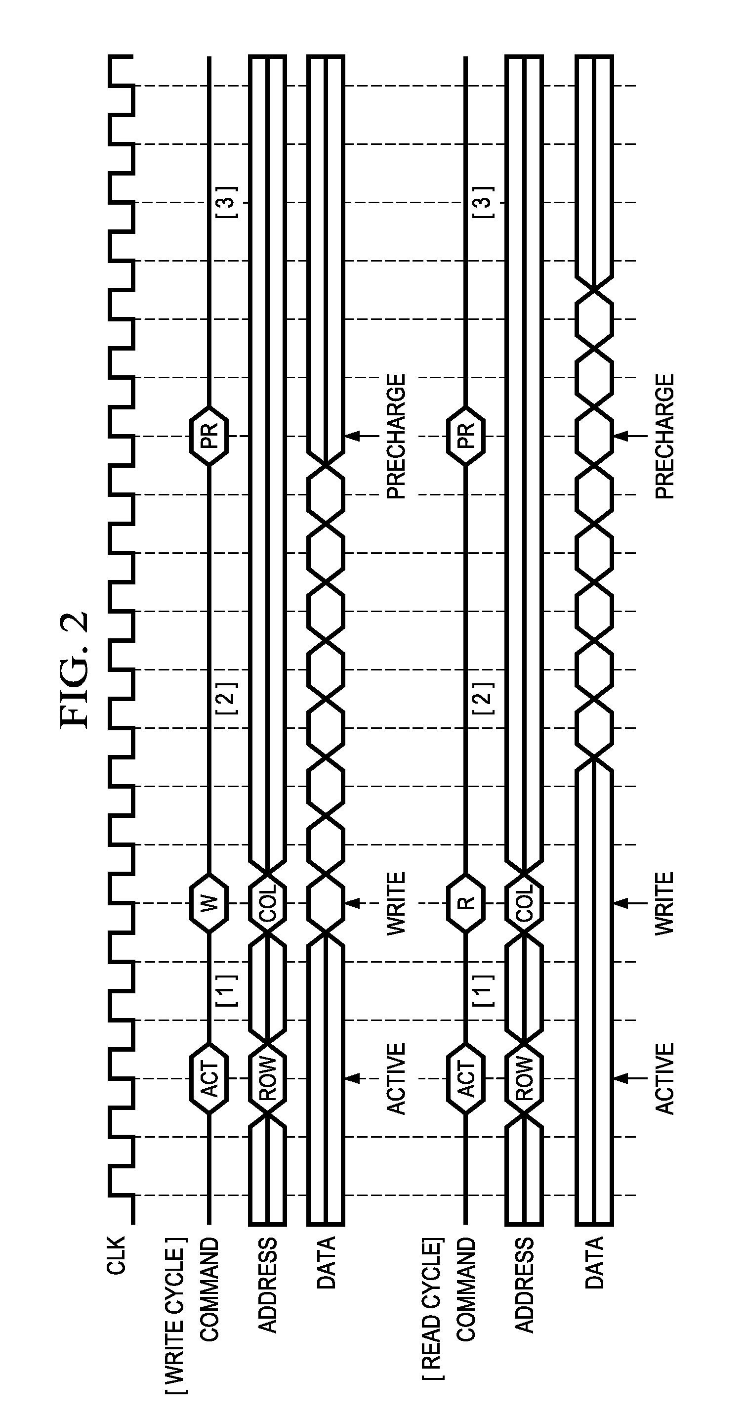
[0095]FIGS. 14 and 15 are timing diagrams illustrating the protocol for avoiding competition between access of SDRAM 20 and access of FLASH 22 in the bus shared system in Embodiments 2 and 3. FIG. 14 is a diagram illustrating write access as the access of SDRAM 20, and read access as the access to FLASH 22. As shown in FIG. 15, the access to SDRAM 20 is read access, and the access to FLASH 22 is the read access.
[0096]As shown in the figures, from before the end of transfer of the write data (#1 . . . #N) on the side of SDRAM 20 on data bus D-Bus 1, it is possible to output the data read to data bus D-Bus 2 from FLASH 22. As a resul...
PUM
 Abstract
Description
Claims
Application Information
 - R&D
- Intellectual Property
- Life Sciences
- Materials
- Tech Scout
- Unparalleled Data Quality
- Higher Quality Content
- 60% Fewer Hallucinations
Browse by: Latest US Patents, China's latest patents, Technical Efficacy Thesaurus, Application Domain, Technology Topic, Popular Technical Reports.
© 2025 PatSnap. All rights reserved.Legal|Privacy policy|Modern Slavery Act Transparency Statement|Sitemap|About US| Contact US: help@patsnap.com


