Elastic wave filter device and duplexer

Active Publication Date: 2015-06-04
MURATA MFG CO LTD
View PDF4 Cites 10 Cited by
  • Summary
  • Abstract
  • Description
  • Claims
  • Application Information

AI Technical Summary

Benefits of technology

[0013]In another certain aspect of the elastic wave filter device according to a preferred embodiment of the present invention, the shield electrode is electrically connected to an end portion of the parallel arm resonator that is to be connected to the ground potential. This makes it possible to share a common terminal for use as a terminal of the parallel arm resonator connected to the ground potential and as a portion of the shield electrode connected to the ground potential. Accordingly, the number of terminals configured to connect to the ground potential is reduced.
[0014]In still another certain aspect of the elastic wave filter device according to a preferred embodiment of the present invention, the first inductor and the second inductor are separated in a lateral direction in/on the board, and the shield electrode is disposed between the first inductor and the second inductor that are separated in the lateral direction. This suppresses the electromagnetic coupling between the first inductor and the second inductor with the shield electrode effectively.
[0015]In another certain aspect of the elastic wave filter device according to a preferred embodiment of the present invention, the first inductor and the second inductor are separated in a thickness direction of the board, and the shield electrode is disposed between the first inductor and the second inductor that are separated in the thickness direction. In this case, the first inductor and the second inductor are separated in the thickness direction. Thus, the planar shape of the elastic wave filter device is reduced.
[0016]In still another certain aspect of the elastic wave filter device according to a preferred embodiment of the present invention, the first inductor is connected in parallel to the series arm resonator that is closest to one of

Problems solved by technology

In the configuration described in the Japanese Unexamined Patent Application Publication No. 2010-109694, there is a problem that attenuation at a stopband near a passband of the elastic wave

Method used


Image

  • Elastic wave filter device and duplexer
  • Elastic wave filter device and duplexer
  • Elastic wave filter device and duplexer

Examples


Embodiment Construction

[0028]Hereinafter the present invention is disclosed in detail by describing specific preferred embodiments of the present invention with reference to the drawings.

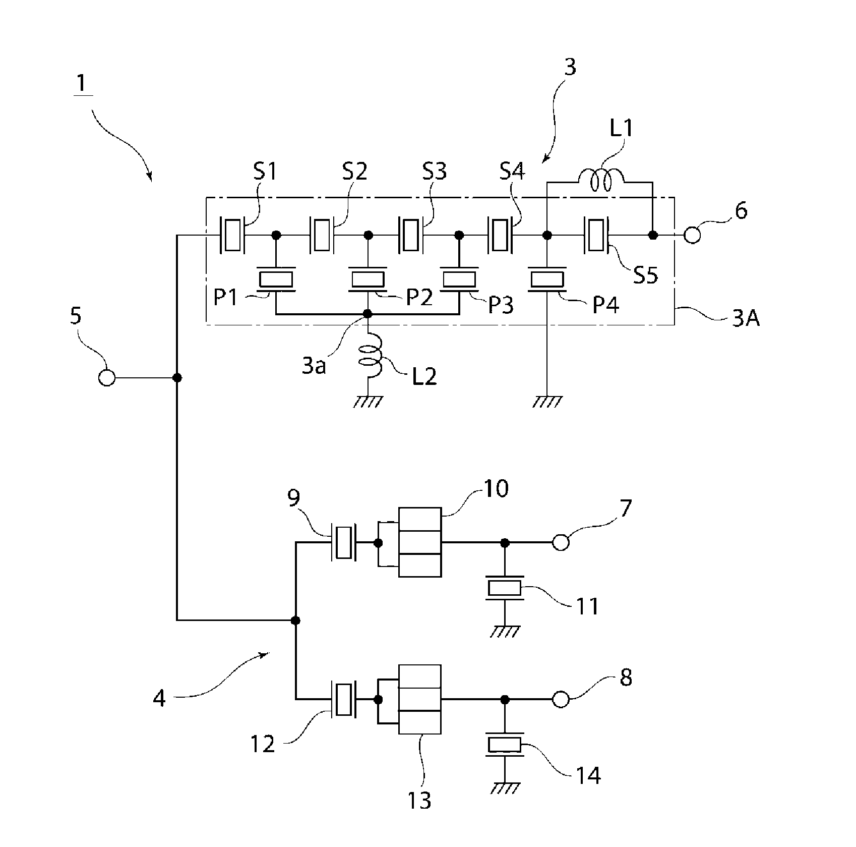
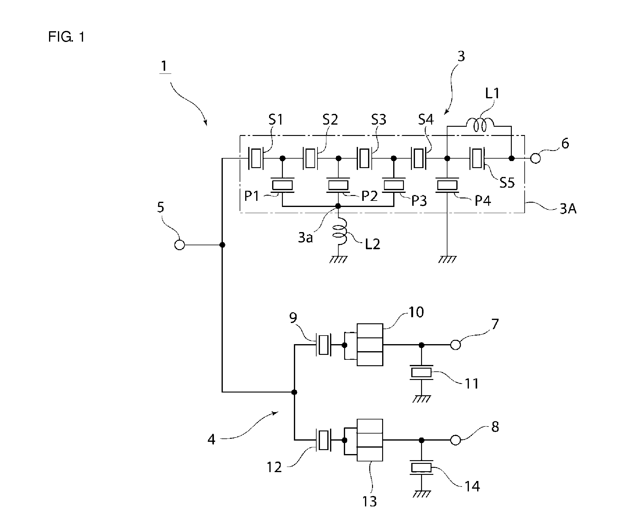
[0029]FIG. 1 is a circuit diagram of a duplexer including an elastic wave filter device according to a preferred embodiment of the present invention.

[0030]In a duplexer 1 of the present preferred embodiment, a transmission filter 3 is provided between an antenna terminal 5 and a transmitter terminal 6. A reception filter 4 is connected between the antenna terminal 5 and first and second receiver terminals 7, 8.

[0031]The transmission filter 3 includes an elastic wave filter element chip 3A having a ladder circuit configuration. In FIG. 1, a portion inside the elastic wave filter element chip 3A is surrounded by a dashed-dotted line. In other words, a plurality of series arm resonators S1 to S5 are connected in series to each other in a series arm connecting the antenna terminal 5 and the transmitter terminal 6. A plurality...


PUM


Abstract

In an elastic wave filter device, an elastic wave filter element chip is mounted on a board. In the elastic wave filter element chip, a ladder filter including a plurality of series arm resonators and a plurality of parallel arm resonators are provided. In/on the board, a first inductor connected in parallel to the series arm resonator and a second inductor connected between the parallel arm resonators P1-P3 and a ground potential are provided. In/on the board, a shield electrode is located between the first inductor and the second inductor.

Description

BACKGROUND OF THE INVENTION[0001]1. Field of the Invention[0002]The present invention relates to elastic wave filter devices having ladder circuit configurations, and more specifically, elastic wave filter devices in which elastic wave filter chips are mounted on boards.[0003]2. Description of the Related Art[0004]Conventionally, elastic wave filters having ladder circuit configurations have been widely used as transmission filters of duplexers in cellular phones. For example, the following Japanese Unexamined Patent Application Publication No. 2010-109694 discloses a duplexer including a transmission filter composed of an elastic wave filter having a ladder circuit configuration and a reception filter composed of a longitudinally coupled resonator-type elastic wave filter.[0005]In the transmission filter of duplexer described in the Japanese Unexamined Patent Application Publication No. 2010-109694, a plurality of series arm resonators is formed in a series arm. A bridging inductan...

Claims


Application Information

Patent Timeline
IPC IPC(8): H03H9/24
CPCH03H9/25H03H9/24H03H7/463H03H9/0566H03H9/542H03H9/706H03H9/725H03H2001/0085H03H9/568H03H9/605H03H9/6483H03H9/0576
Inventor KUZUSHITA, TAKUMATANIGUCHI, YASUMASAMIYAKE, TAKASHI
Owner MURATA MFG CO LTD
Why Eureka
Try Eureka