Moving image coding method and apparatus for determining a position of a macro block which is intra-coded or inter-coded

Inactive Publication Date: 2007-08-14
COLLABO INNOVATIONS INC
View PDF14 Cites 8 Cited by
  • Summary
  • Abstract
  • Description
  • Claims
  • Application Information

AI Technical Summary

Benefits of technology

[0018]The object of the invention is to provide moving image coding method and apparatus, performing compression coding for moving images with intra coding and inter coding, which enable the reduction of the capacity of a reference image memory with keeping suitable coding efficiency and suitable image quality according to use to reduce the cost of the moving image coding apparatus.

Problems solved by technology

It means limitation to predictive coding which is the base of the technique that the capacity of the reference image memory is reduced, as a result, the efficiency of coding is deteriorated and coding quantity is increased.
In a moving image coding apparatus for a video screen, in the case a reference image memory corresponding to normal screen size is provided, a mass-storage reference image memory according to large screen size is further required to be provided to also enable the moving image coding of the large screen size (a large number of pixels) in the same apparatus and there is a problem that the system cost is increased.

Method used


Image

  • Moving image coding method and apparatus for determining a position of a macro block which is intra-coded or inter-coded
  • Moving image coding method and apparatus for determining a position of a macro block which is intra-coded or inter-coded
  • Moving image coding method and apparatus for determining a position of a macro block which is intra-coded or inter-coded

Examples


first embodiment

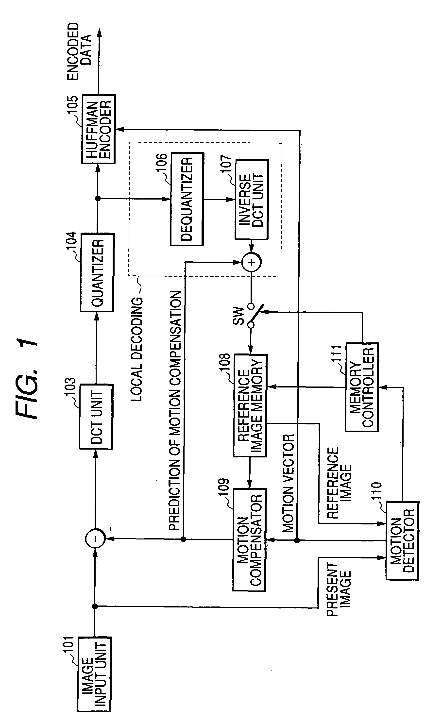
[0126]FIG. 1 is a block diagram showing the configuration of a moving image coding apparatus equivalent to a first embodiment of the invention. In FIG. 1, the same reference number is allocated to the same part as the part in the conventional moving image coding apparatus shown in FIG. 30.

[0127]As shown in FIG. 1, a reference number 101 denotes an image input unit, 103 denotes a DCT unit that performs orthogonal transformation, 104 denotes a quantizer, 105 denotes a Huffman encoder that executes variable-length coding, 106 denotes a dequantizer, 107 denotes a inverse DCT unit that performs inverse orthogonal transformation, 108 denotes a reference image memory, 109 denotes a motion compensator, 110 denotes a motion detector and 111 denotes a memory controller.

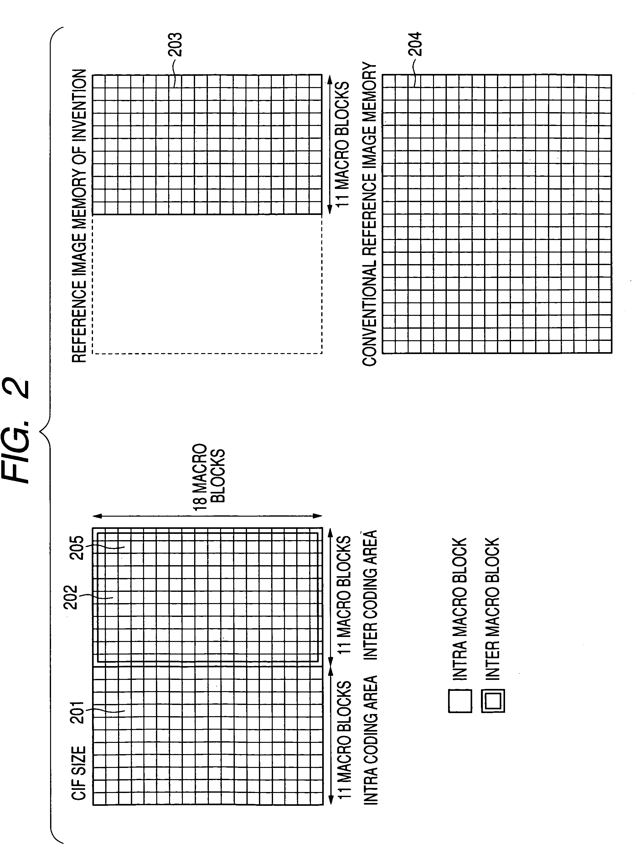
[0128]In the memory controller 111, the number of maximum macro blocks for which inter coding is performed in one image frame is set to a smaller value than the number of macro blocks configuring an image frame and in a range o...

second embodiment

[0139]FIG. 3 is a block diagram showing the configuration of a moving image coding apparatus equivalent to a second embodiment of the invention. As shown in FIG. 3, the same reference number is allocated to the same part as the part in the moving image coding apparatus equivalent to the first embodiment shown in FIG. 1.

[0140]In the moving image coding apparatus in this embodiment, the arrangement of a macro block position for which intra coding is performed and a macro block position for which inter coding is performed is specified from an external. In FIG. 3, in addition to the configuration shown in FIG. 1, an inter coding instruction signal 301 from the external is input to a memory controller 111.

[0141]As there is a case that coding efficiency is deteriorated when a macro block position for which intra coding is performed and a macro block position for which inter coding is performed are fixed on the screen as shown in FIG. 2 depending upon a photographed image, a user judges a ...

third embodiment

[0149]FIG. 5 is a block diagram showing the configuration of a moving image coding apparatus equivalent to a third embodiment of the invention. In FIG. 5, the same reference number is allocated to the same part as that in the moving image coding apparatus equivalent to the first embodiment shown in FIG. 1.

[0150]In the moving image coding apparatus in this embodiment, a macro block position for which intra coding or inter coding is performed is determined based upon the quantity of codes in an image frame. In FIG. 5, in addition to the configuration shown in FIG. 1, a code quantity counter 501 for counting the quantity of codes in an image frame is provided and a code quantity threshold 502 is input from an external.

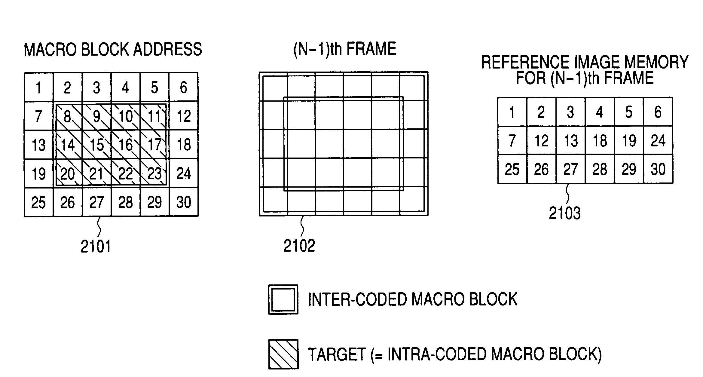
[0151]FIG. 6 is an explanatory drawing for explaining recording control over a reference image memory in this embodiment. As shown in FIG. 6, suppose that a group of macro blocks 601 for which intra coding is performed is located on the left side of a frame in the (N−1)th...


PUM


Abstract

A memory controller controls so that the number of maximum macro blocks for which inter coding is performed in one image frame is set to a smaller value than the number of macro blocks configuring the image frame, the capacity of the reference image memory is reduced to capacity for the maximum macro blocks for which inter coding is performed, macro block positions for which intra coding and inter coding are performed in the next frame are determined based upon image information and the quantity of codes in the coding of a present image and reference image macro blocks equivalent to only macro block positions for which inter coding is determined to be performed in the next frame are stored in the reference image memory.

Description

BACKGROUND OF THE INVENTION[0001]1. Field of the Invention[0002]The present invention relates to moving image coding method and apparatus for executing the compression coding of a moving image by suitably switching intra coding which utilizes spatial redundancy in a frame and inter coding which utilizes temporal redundancy between frames.[0003]2. Description of the Related Art[0004]FIG. 30 is a block diagram showing an example of the configuration of a conventional moving image apparatus (encoder). As shown in FIG. 30, a reference number 101 denotes an image input unit, 103 denotes a discrete cosine transform (DCT) unit for performing orthogonal transformation, 104 denotes a quantizer, 105 denotes a Huffman encoder for executing variable-length coding, 106 denotes a dequantizer, 107 denotes a inverse DCT unit for performing inverse orthogonal transformation, 108 denotes a reference image memory, 109 denotes a motion compensator, 110 denotes a motion detector and 3011 denotes a memor...

Claims


Application Information

Patent Timeline
IPC IPC(8): G06K9/36G06K9/00H04N19/50G06K9/46H04N19/102H04N19/105H04N19/12H04N19/134H04N19/136H04N19/152H04N19/162H04N19/176H04N19/196H04N19/423H04N19/426H04N19/503H04N19/513H04N19/593H04N19/60H04N19/61H04N19/625H04N19/65H04N19/91
CPCH04N19/61H04N19/142H04N19/426H04N19/164H04N19/152
Inventor YAMAMOTO, TAKAHIRONAKAHARA, MITSUYAINOKUMA, KAZUYUKIKITAMURA, SHINJI
Owner COLLABO INNOVATIONS INC
Why Eureka
Try Eureka