Oscillator

a technology of oscillator and oscillator, which is applied in the direction of pulse generator, pulse technique, electric pulse generator circuit, etc., can solve the problems of insufficient amplification of oscillator signal, consumption of more than necessary power, and slow clock rate of amplifying fet, so as to improve oscillator signal characteristics and reduce power consumption.

Inactive Publication Date: 2005-12-15
ROHM CO LTD
View PDF5 Cites 2 Cited by
  • Summary
  • Abstract
  • Description
  • Claims
  • Application Information

AI Technical Summary

Benefits of technology

[0007] The present invention has been made in view of the foregoing circumstances and an object thereof is to provide an osci

Problems solved by technology

At high oscillation frequencies, however, there are generally the following problems to be solved.
For example, when an oscillation signal at a high oscillation frequency is to be generated and to be further amplified by a field effect transistor (FET) (hereinafter referred to as “amplifying FET”), any small current to the amplifying FET slows the clock rate of the amplifying FET, which resu

Method used


Image

  • Oscillator
  • Oscillator
  • Oscillator

Examples


first embodiment

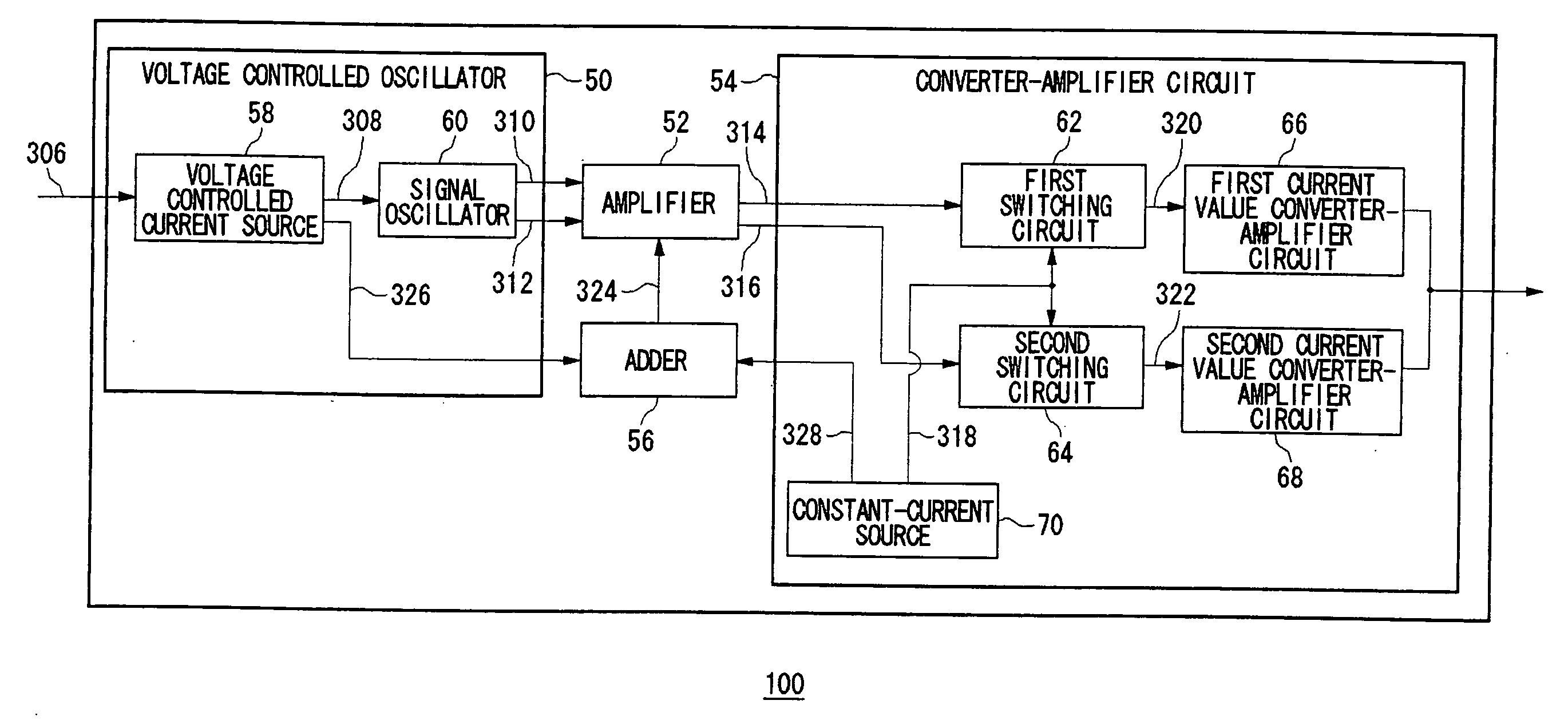
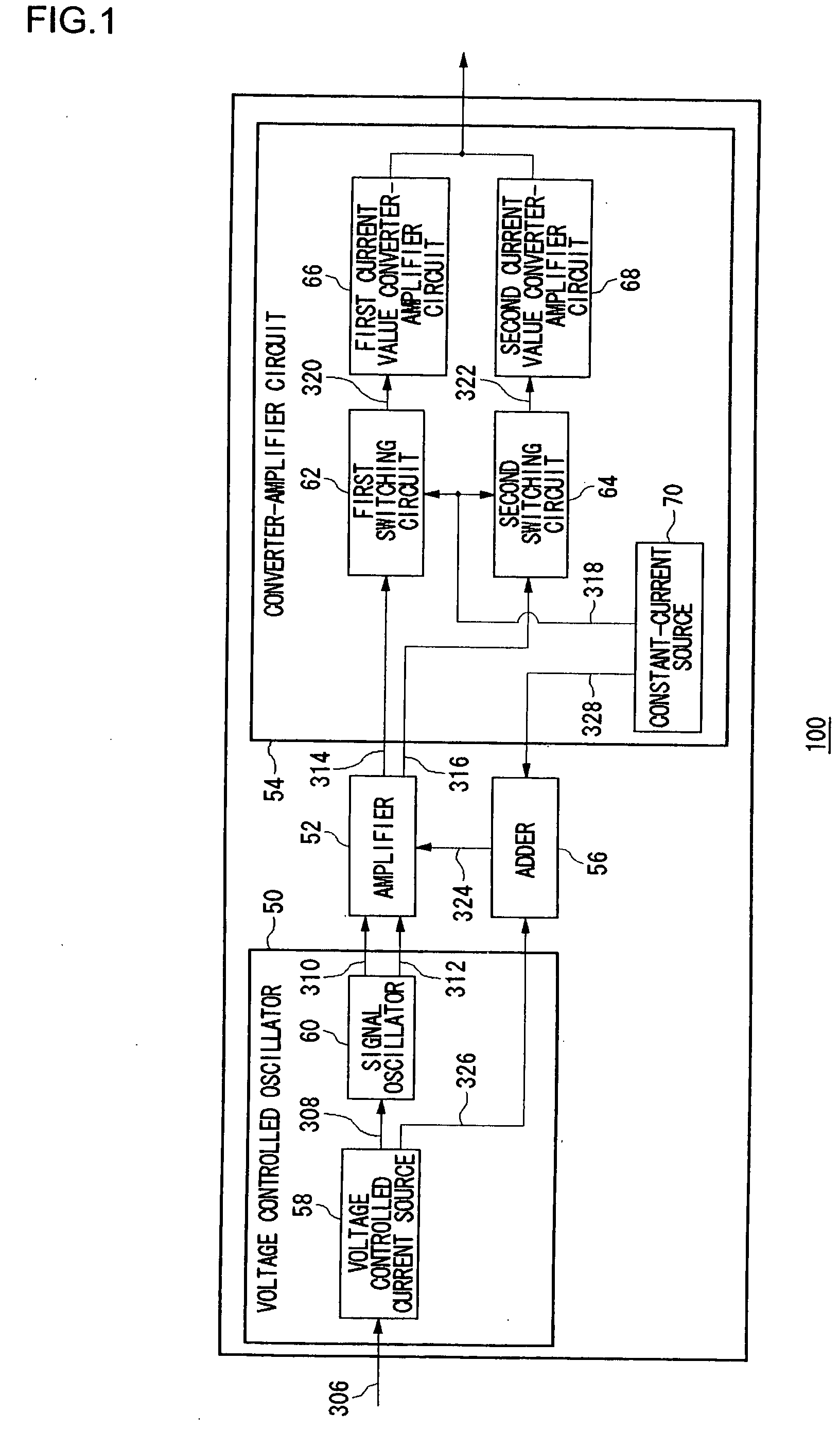
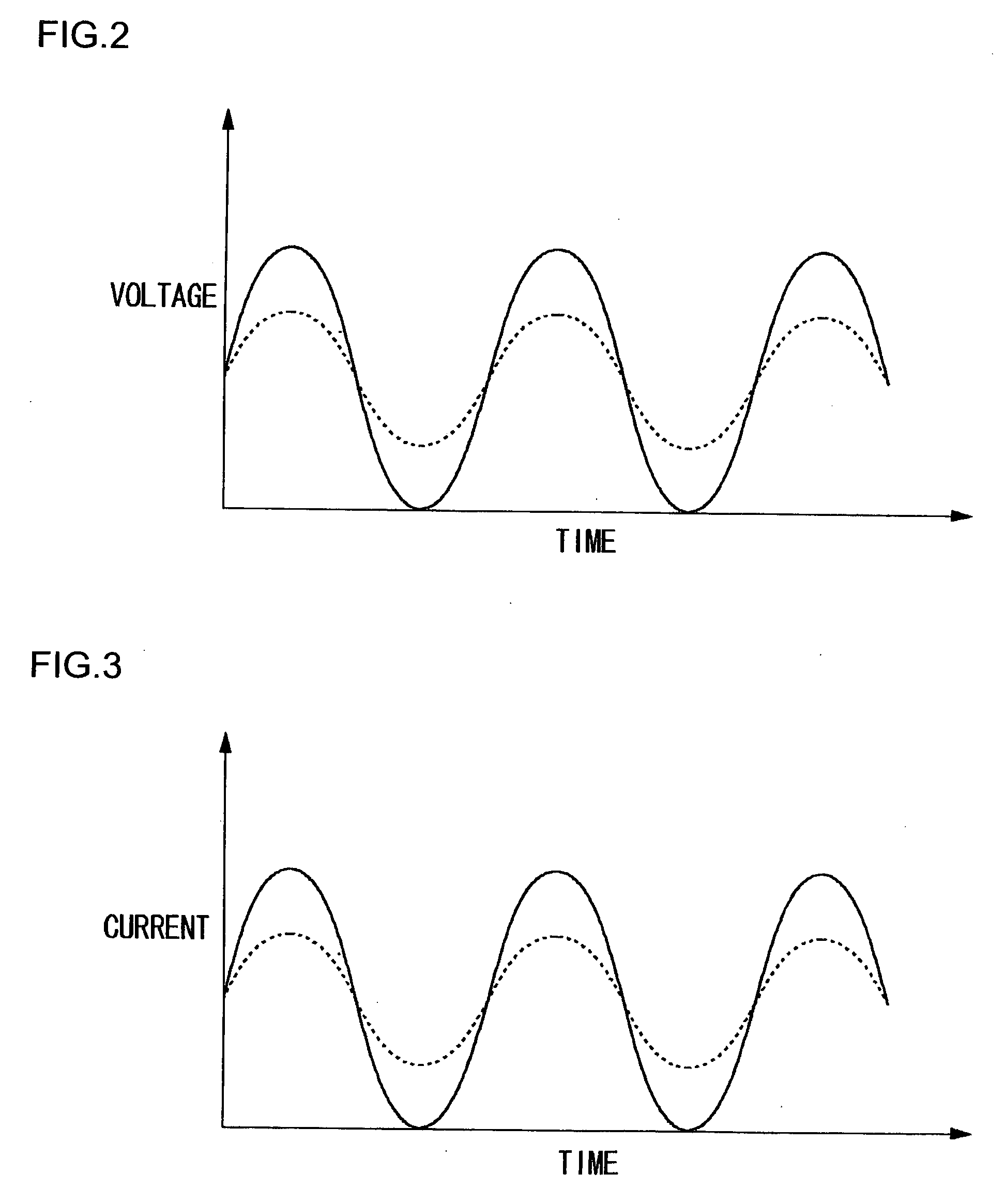
[0026] A first embodiment relates to a high-frequency oscillator so structured that a manufacturer can mass-produce a general-purpose version capable of generating oscillation signals in a wide range of oscillation frequencies and moreover a user can set predetermined oscillation frequencies for such a circuit before incorporating it into predetermined equipment. A high-frequency oscillator according to the present embodiment changes the oscillation frequency of an oscillation signal in response to applied control voltage. For example, the circuit raises the oscillation frequency in response to a higher control voltage and lowers it in response to a lower control voltage. Also, the amplitude of the voltage of an oscillation signal is sufficiently amplified by an amplifying FET, and the voltage of the amplified oscillation signal is converted into a current. In particular, a high-frequency oscillator according to this embodiment, which increases the amount of current flowing to the a...

second embodiment

[0043] A high-frequency oscillator according to a second embodiment is a circuit similar to that of the first embodiment. Though a high-frequency oscillator is explained using function blocks in the first embodiment, a high-frequency oscillator according to the second embodiment will be explained with a circuit configuration such as an FET.

[0044]FIG. 4 shows a high-frequency oscillator 100 according to a second embodiment of the present invention. It is to be noted here that the same function blocks and signals in FIG. 4 as those in FIG. 1 are given the same reference numerals as in FIG. 1.

[0045] A variable current source 72 delivers a current that varies according to a controlled voltage 306. Transistors Tr1, Tr2 and Tr3 constitute a current mirror circuit. The oscillator equivalent current 326 is delivered from the transistor Tr2 whereas the oscillator drive current 308 is delivered from the transistor Tr3. As described above, the oscillator drive current 308, the oscillator equ...

third embodiment

[0057] In this third embodiment, a structure of apparatus or LSI to which a high-frequency oscillator according to the first or second embodiment is implemented or applied will be described.

[0058]FIG. 5A illustrates a structure of an optical pickup 200 among applied examples of the high-frequency oscillator 100 according to the third embodiment. The optical pickup 200 includes a high-frequency oscillator 100, a semiconductor laser chip 102, a photodiode 104 for use with a monitor and a light receiving photodiode 108. The optical pickup 200 reads signals out of or write them to a disk, which is a recording medium, in information record / reproduce equipment such as an optical disk device or magneto-optical disk unit.

[0059] The semiconductor laser chip 102 emits laser beams in response to current supplied from a high-frequency oscillator 100 described later. Based on a control signal indicated by voltage from an automatic power control (APC) circuit described later, the high-frequency...


PUM


Abstract

A voltage controlled current source outputs oscillator drive current and oscillator equivalent current. A signal oscillator outputs first source oscillation signal and second source oscillation signal. A differential amplifier outputs first amplification oscillation signal and second amplification oscillation signal. First switch circuit and second switch circuit output first current oscillation signal and second current oscillation signal, respectively. A first current value converter-amplifier circuit converts a value of the first current oscillation signal whereas a second current value converter-amplifier circuit converts a value of the second current oscillation signal, so that the thus converted values become output current finally. An adder outputs to the differential amplifier a differential amplifier drive current in which equivalent current for use with conversion is added up with the oscillator equivalent current outputted from the voltage controlled current source.

Description

BACKGROUND OF THE INVENTION [0001] 1. Field of the Invention [0002] The present invention relates to oscillators, and it particularly relates to an oscillator in which the frequency of oscillation can be varied. [0003] 2. Description of the Related Art [0004] A voltage controlled oscillator is used in optical pickups or phase-locked loops (PLL), for instance. Generally, an oscillation frequency is adjusted according to a control voltage applied and then a signal of the thus adjusted oscillation frequency is outputted. In an example of a conventional voltage controlled oscillator, an inverting amplifier, a first charge / discharge circuit and a second charge / discharge circuit are electrically coupled to form a circuit. In this structure, the phase of an inverted voltage signal from the inverting amplifier is delayed in stages at the first and the second charge / discharge circuit and the output of the second charge / discharge circuit is again inputted to the inverting amplifier. After a f...

Claims


Application Information

Patent Timeline
IPC IPC(8): H03K3/03H03L7/00H03L7/099
CPCH03K3/0322H03L7/0995
Inventor KAKIUCHI, TAKAOWAKII, TAKESHIMARUYAMA, SHO
Owner ROHM CO LTD
Why Eureka
Try Eureka