Polar modulation transmission circuit and polar modulation transmission method

a transmission circuit and polar modulation technology, applied in the direction of amplifiers, amplitude to angle modulation conversion, electrical equipment, etc., can solve the problems of radio performance degradation such as aclr (adjacent channel lockage power ratio) in the transmitter, and achieve the effect of suppressing the degradation of signal quality

Inactive Publication Date: 2012-05-10
PANASONIC CORP
View PDF3 Cites 3 Cited by
  • Summary
  • Abstract
  • Description
  • Claims
  • Application Information

AI Technical Summary

Benefits of technology

[0015]According to the present invention, it is possible to compensate the distortion component caused by the individual variation of the amplifier, with the small man-hour, to effectively suppress the degradation of the signal quality.

Problems solved by technology

As a result, radio performance such as an ACLR (Adjacent Channel Lockage Power Ratio) is degraded in a transmitter.

Method used


Image

  • Polar modulation transmission circuit and polar modulation transmission method
  • Polar modulation transmission circuit and polar modulation transmission method
  • Polar modulation transmission circuit and polar modulation transmission method

Examples


embodiment 1

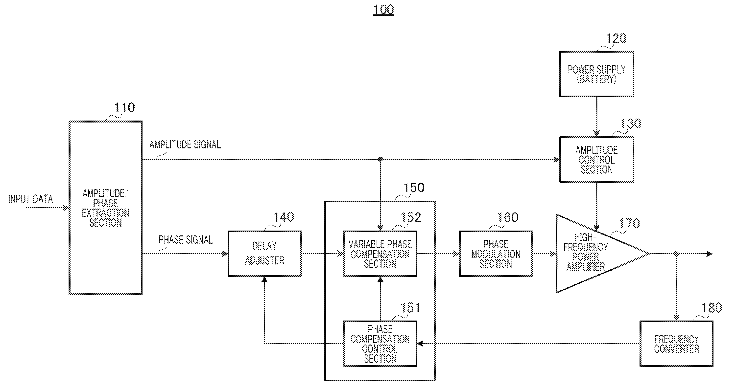
[0034]FIG. 4 illustrates a configuration of a main part of polar modulation transmission circuit (hereinafter simply referred to as a “transmission circuit”) 100 according to the present embodiment of the present invention.

[0035]Amplitude / phase extraction section 110 inputs modulation data (hereinafter referred to as input data) as data to be transmitted, and extracts an amplitude signal r(t) and a phase signal φ(t) from the input data. Amplitude / phase extraction section 110 outputs the amplitude signal r(t) to amplitude control section 130 and variable phase compensation section 152 of phase compensation section 150. Amplitude / phase extraction section 110 outputs the phase signal φ(t) to delay adjuster 140.

[0036]Power supply (battery) 120 supplies a power supply voltage to amplitude control section 130.

[0037]Amplitude control section 130 biases the power supply voltage, which is supplied from power supply (battery) 120, according to the input amplitude signal r(t) and outputs a vol...

embodiment 2

[0092]In the present embodiment, a polar modulation transmission circuit that sets the delay amount of delay adjuster 140 to an optimum value based on [1] the shape of the AM-PM in the compensation characteristic and [2] the change amount of the shape of the AM-PM in the compensation characteristic will be described.

[0093]FIG. 14 illustrates a configuration of a main part of a polar modulation transmission circuit (hereinafter simply referred to as a “transmission circuit”) according to the present embodiment of the present invention. In the transmission circuit of the present embodiment of FIG. 14, the component common to that of FIG. 4 is designated by the same numeral, and the description is omitted. Transmission circuit 200 of FIG. 14 differs from transmission circuit 100 of FIG. 4 in that transmission circuit 200 includes phase compensation section 210 instead of phase compensation section 150.

[0094]Phase compensation section 210 includes phase compensation control section 151,...

embodiment 3

[0105]Generally, when an ambient temperature is changed, a characteristic of the high-frequency power amplifier varies in consideration of an operating environment of the transmission circuit. For example, in the high-frequency power amplifier including an HBT (Heterojunction Bipolar Transistor), a relationship (AM-PM characteristic) between the power supply voltage supplied to the power supply voltage of the high-frequency power amplifier and the passage phase varies by the change of the temperature. That is, the passage phase varies by the temperature even if the same power supply voltage is supplied to the high-frequency power amplifier. Because the AM-PM characteristic of the high-frequency power amplifier is degraded by the variation in passage phase, for example, unfortunately a disturbing signal is generated to the adjacent frequency band to degrade the ACLR. Therefore, it is necessary to adaptively perform the temperature compensation according to the temperature change. In ...


PUM


Abstract

Disclosed is a polar modulation transmission circuit wherein distortion components resulting from variations between individual amplifiers are compensated for with few man-hours, and deterioration in signal quality is effectively suppressed. A frequency converter (180) converts the frequency of an output signal of a high frequency power amplifier (170) and outputs a frequency domain signal, and a phase compensation unit (150) measures the power level, for each delay amount, at a low frequency band and high frequency band wherein the detuning frequency from the frequency domain signal is the same, calculates the “unlevel amount” (relative level difference) between the power level of the low frequency band and power level of the high frequency band for each delay amount, and determines the compensation characteristics on the basis of the relationship of the unlevel amount (relative level difference) to the delay amount. Then, the phase compensation unit (150) compensates for the phase signal by adding to the phase signal the phase compensation amount, in the determined compensation characteristics, that corresponds to the amplitude signal.

Description

TECHNICAL FIELD[0001]The present invention relates to a transmission circuit and a transmission method, which are used in communication devices such as a mobile phone and a wireless LAN, particularly to a polar modulation transmission circuit and a polar modulation transmission method for performing compensation to a phase.BACKGROUND ART[0002]In design of the conventional transmission apparatus, generally there is a trade-off relationship between efficiency and linearity. However, in the transmitting apparatus, recently there is proposed a technology in which a balance between the high efficiency and the linearity can be established using polar modulation.[0003]As to the conventional polar modulation transmission circuit, for example, Patent Literature 1 discloses a transmission circuit. FIG. 1 is a block diagram illustrating an example of a configuration of conventional transmission circuit 10 disclosed in Patent Literature 1. In FIG. 1, conventional transmission circuit 10 include...

Claims


Application Information

Patent Timeline
Patent Type & Authority Applications(United States)
IPC IPC(8): H03C3/38
CPCH03F1/0205H03F1/3247H03F1/3282H04B2001/0425H03F2201/3233H04B1/0475H03F3/24H03F1/3241
Inventor NAKAMURA, MAKI
Owner PANASONIC CORP
Why Eureka
Try Eureka