Continuously variable transmission

a transmission and variable technology, applied in the field of transmissions, can solve the problems of difficult shifting of the rotational axis of each of the traction rollers, difficult use of iris plates, and limited success of traditional solutions

Inactive Publication Date: 2005-04-14
FALLBROOK INTPROP COMPANY
View PDF99 Cites 122 Cited by
  • Summary
  • Abstract
  • Description
  • Claims
  • Application Information

AI Technical Summary

Problems solved by technology

However, the success of these traditional solutions has been limited.
However, the use of iris plates can be very complicated due to the large number of parts that are required to adjust the iris plates during transmission shifting.
Another difficulty with this transmission is that it has a guide ring that is configured to be predominantly stationary in relation to each of the rollers.
Since the guide ring is stationary, shifting the axis of rotation of each of the

Method used


Image

  • Continuously variable transmission
  • Continuously variable transmission
  • Continuously variable transmission

Examples


Embodiment Construction

” one will understand how the features of the system and methods provide several advantages over traditional systems and methods.

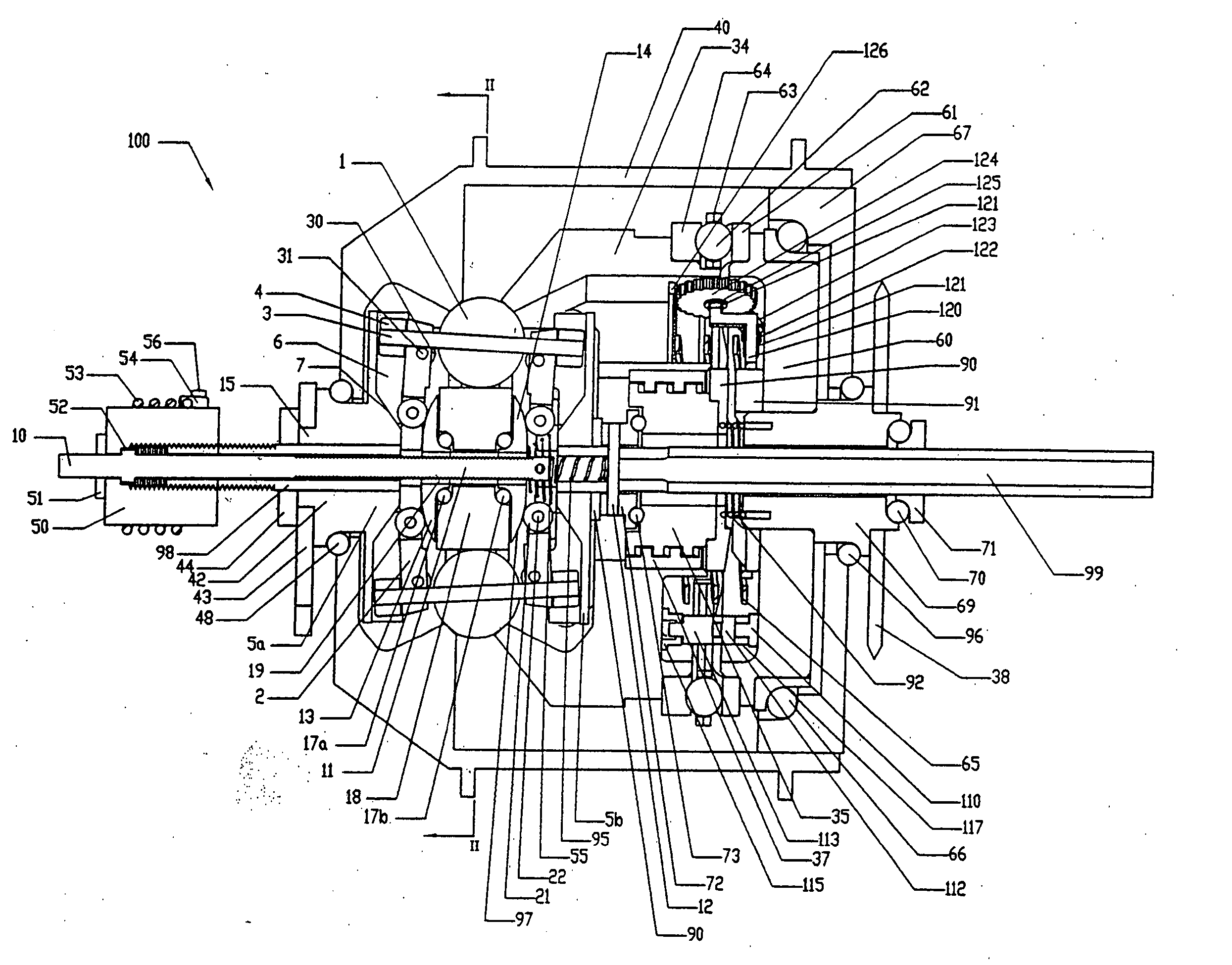
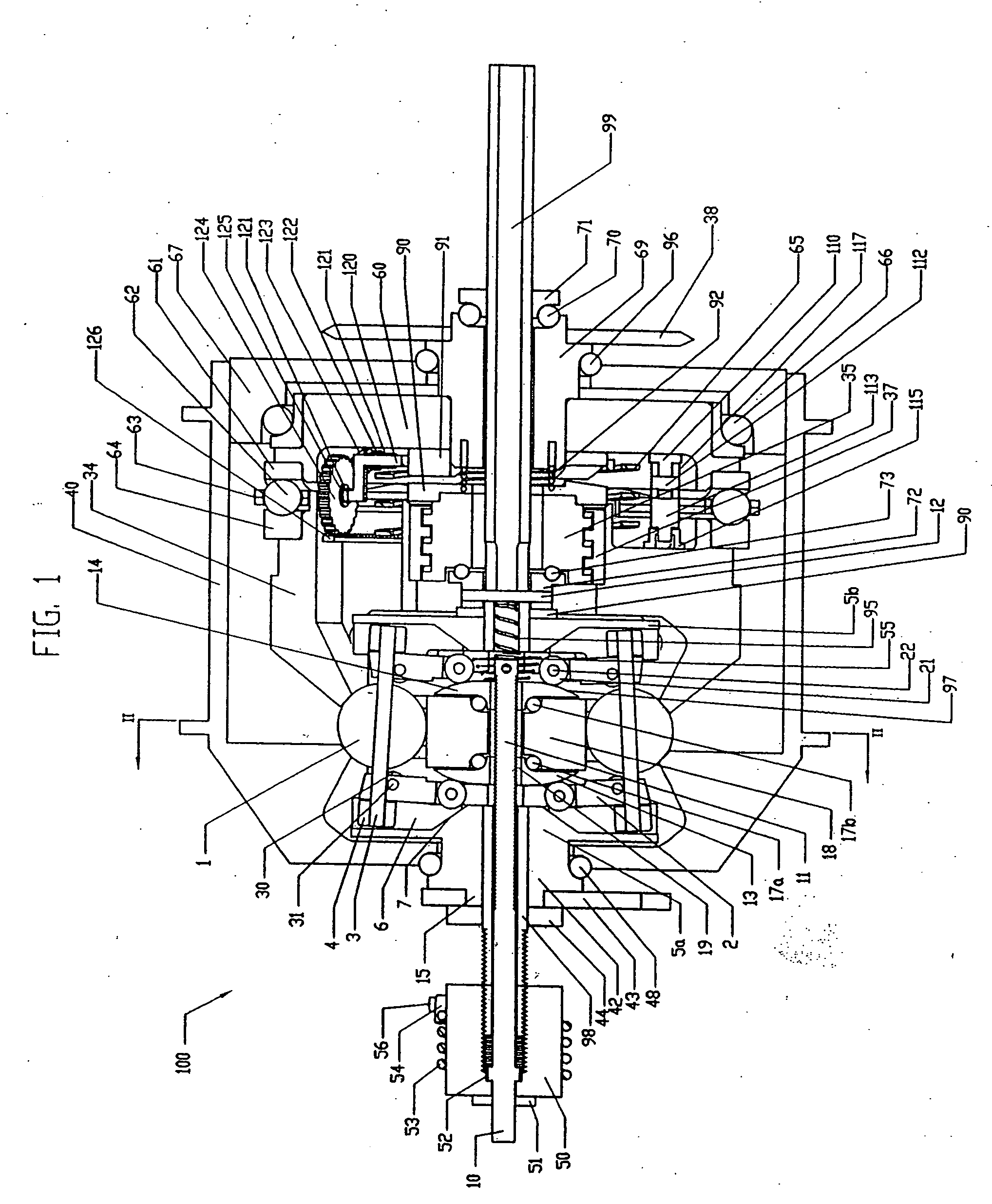
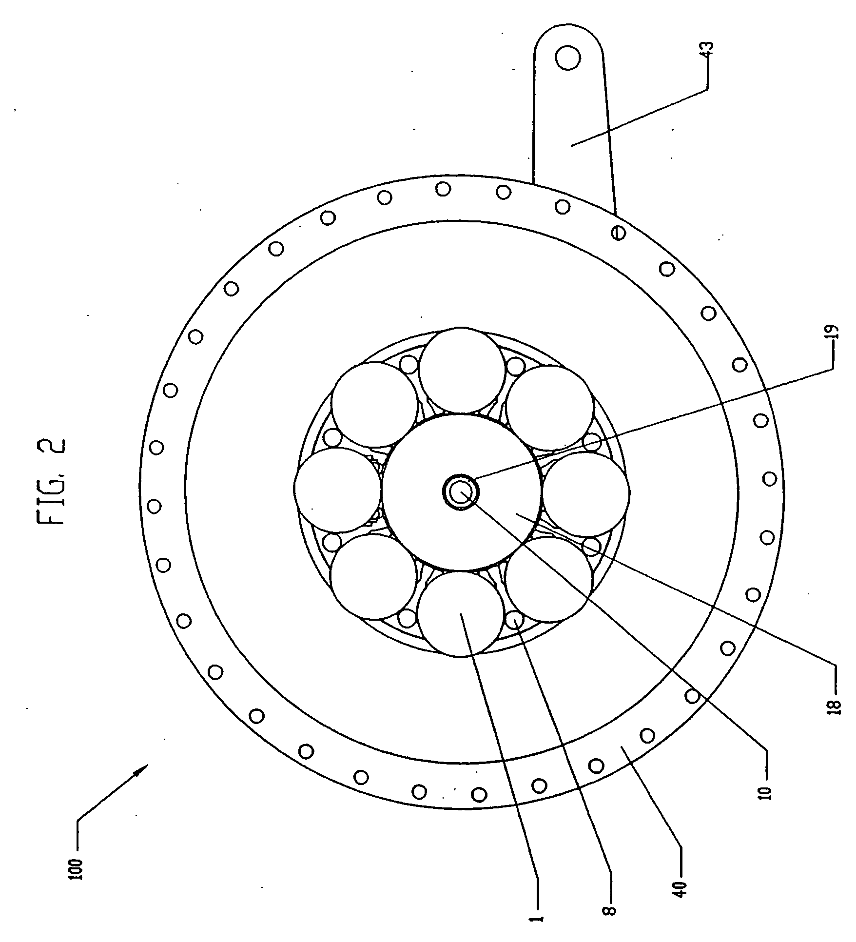
[0010] In one aspect, a continuously variable transmission is disclosed having a longitudinal axis, and a plurality of speed adjusters. Each speed adjuster has a tiltable axis of rotation is located radially outward from the longitudinal axis. Also provided are a drive disk that is annularly rotatable about the longitudinal axis and also contacts a first point on each of the speed adjusters and a support member that is also annularly rotatable about the longitudinal axis. A bearing disk is provided that is annularly rotatable about the longitudinal axis as well, and at least two axial force generators. The axial force generators are located between the drive disk and the bearing disk and each axial force generator is configured to apply an axial force to the drive disk.

[0011] In another aspect, a bearing disk annularly rotatable about the longitudinal axi...


PUM


Abstract

A continuously variable transmission is disclosed for use in rotationally or linearly powered machines and vehicles. The transmission provides a simple manual shifting method for the user. Further, the practical commercialization of traction roller transmissions requires improvements in the reliability, ease of shifting, function and simplicity of the transmission. The present invention includes a continuously variable transmission that may be employed in connection with any type of machine that is in need of a transmission. For example, the transmission may be used in (i) a motorized vehicle such as an automobile, motorcycle, or watercraft, (ii) a non-motorized vehicle such as a bicycle, tricycle, scooter, exercise equipment or (iii) industrial equipment, such as a drill press, power generating equipment, or textile mill.

Description

RELATED APPLICATIONS [0001] This application is a continuation of and claims priority to U.S. application Ser. No. 10 / 770,966 filed on Feb. 3, 2004, which claims priority from U.S. application Ser. No. 10 / 134,097 filed on Apr. 25, 2002, which in turn claims priority from U.S. Provisional Application No. 60 / 286,803, filed Apr. 26, 2001. The entire disclosure of each of those applications is hereby incorporated by reference.BACKGROUND OF THE INVENTION [0002] 1. Field of the Invention [0003] The field of the invention relates generally to transmissions, and more particularly the invention relates to continuously variable transmissions. [0004] 2. Description of the Related Art [0005] The present invention relates to the field of continuously variable transmissions and includes several novel features and inventive aspects that have been developed and are improvements upon the prior art. In order to provide an infinitely variable transmission, various traction roller transmissions in whic...

Claims


Application Information

Patent Timeline
IPC IPC(8): B62M11/12F16H15/32F16H1/00F16H15/28F16H35/00F16H61/662F16H61/664
CPCB62M11/12F16H15/28F16H63/067F16H61/664F16H61/6649F16H15/52F16H15/04
Inventor MILLER, DONALD C.ALLEN, DAVID JOHN
Owner FALLBROOK INTPROP COMPANY
Why Eureka
Try Eureka