Pneumatic stimulator array

a pneumatic stimulus and array technology, applied in the field of pneumatic stimulus arrays, can solve the problems of high cost of implementation, many forms of damage, vibrators, etc., and achieve the effect of reducing the number of valves required to operate the array

Inactive Publication Date: 2005-04-14
HEMBY JR JOSEPH K
View PDF8 Cites 7 Cited by
  • Summary
  • Abstract
  • Description
  • Claims
  • Application Information

AI Technical Summary

Benefits of technology

[0008] Another object of the instant invention is to provide an improved stimulating array where each node is inherently an AND gate and may thereby form an individually addressable node in a larger array, thus reducing the number of valves required to operate the array.
[0011] A further object of the instant invention is to provide an improved stimulating array that is readily manufacturable at low cost.

Problems solved by technology

Spatial disorientation is the cause of a significant number of accidents within the aviation community, and the need to avoid spatial disorientation by attending to attitude instruments visually is a major source of work load for an aviator.
Electrical approaches, however, such as vibrators, etc., are expensive to implement and vulnerable to many forms of damage.

Method used


Image

  • Pneumatic stimulator array
  • Pneumatic stimulator array
  • Pneumatic stimulator array

Examples


Embodiment Construction

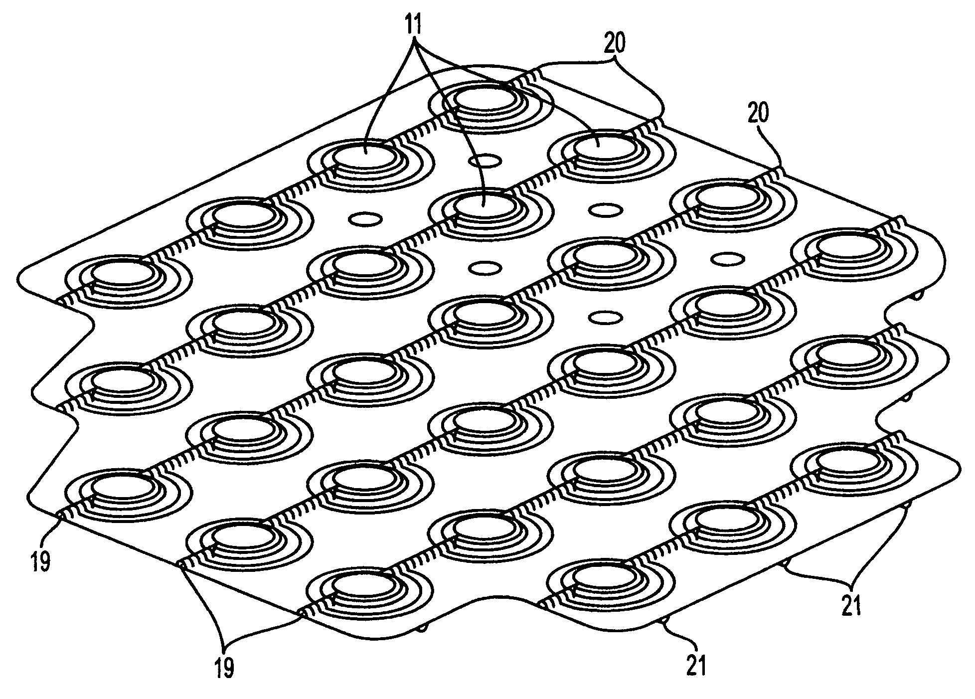
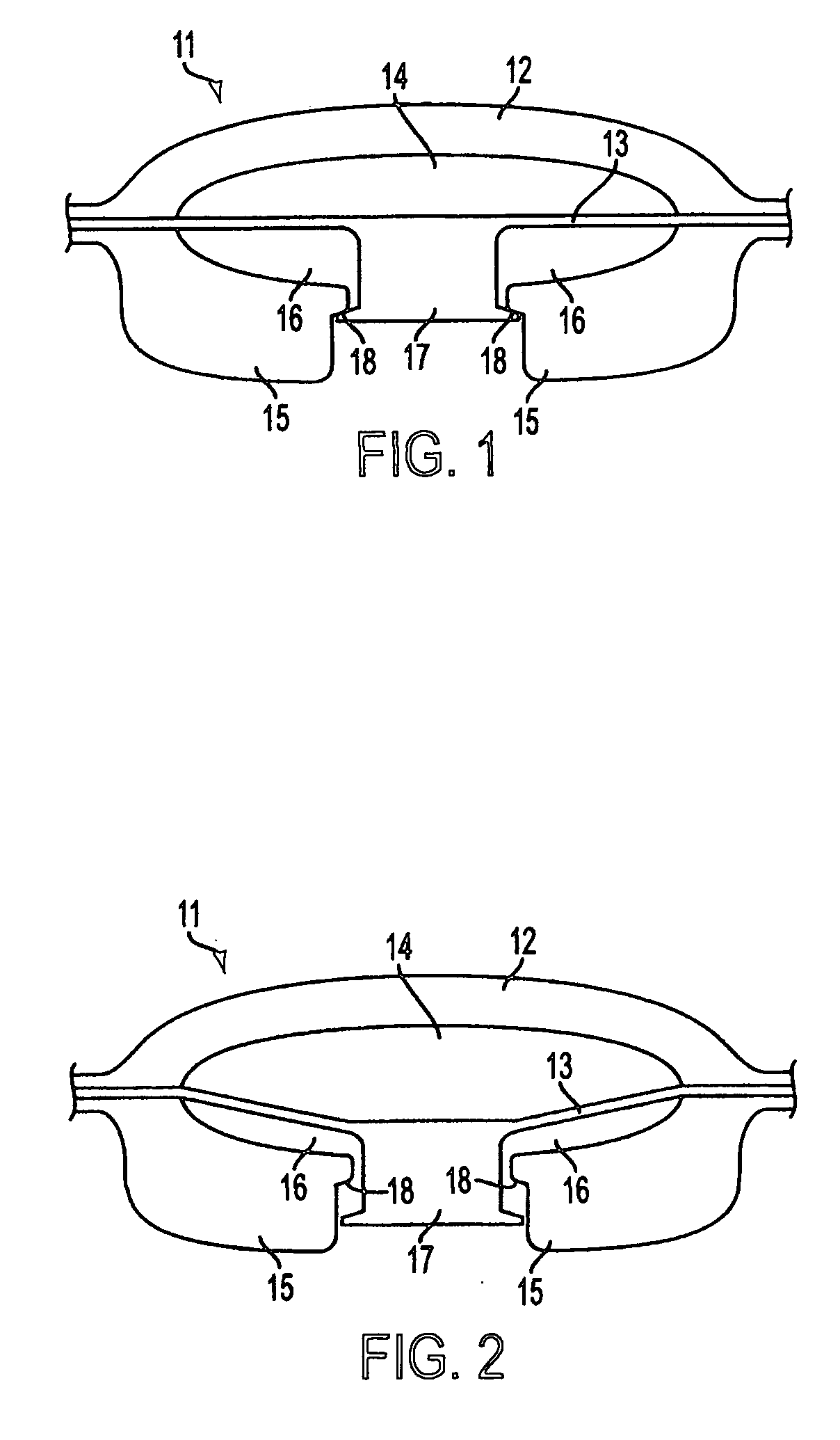
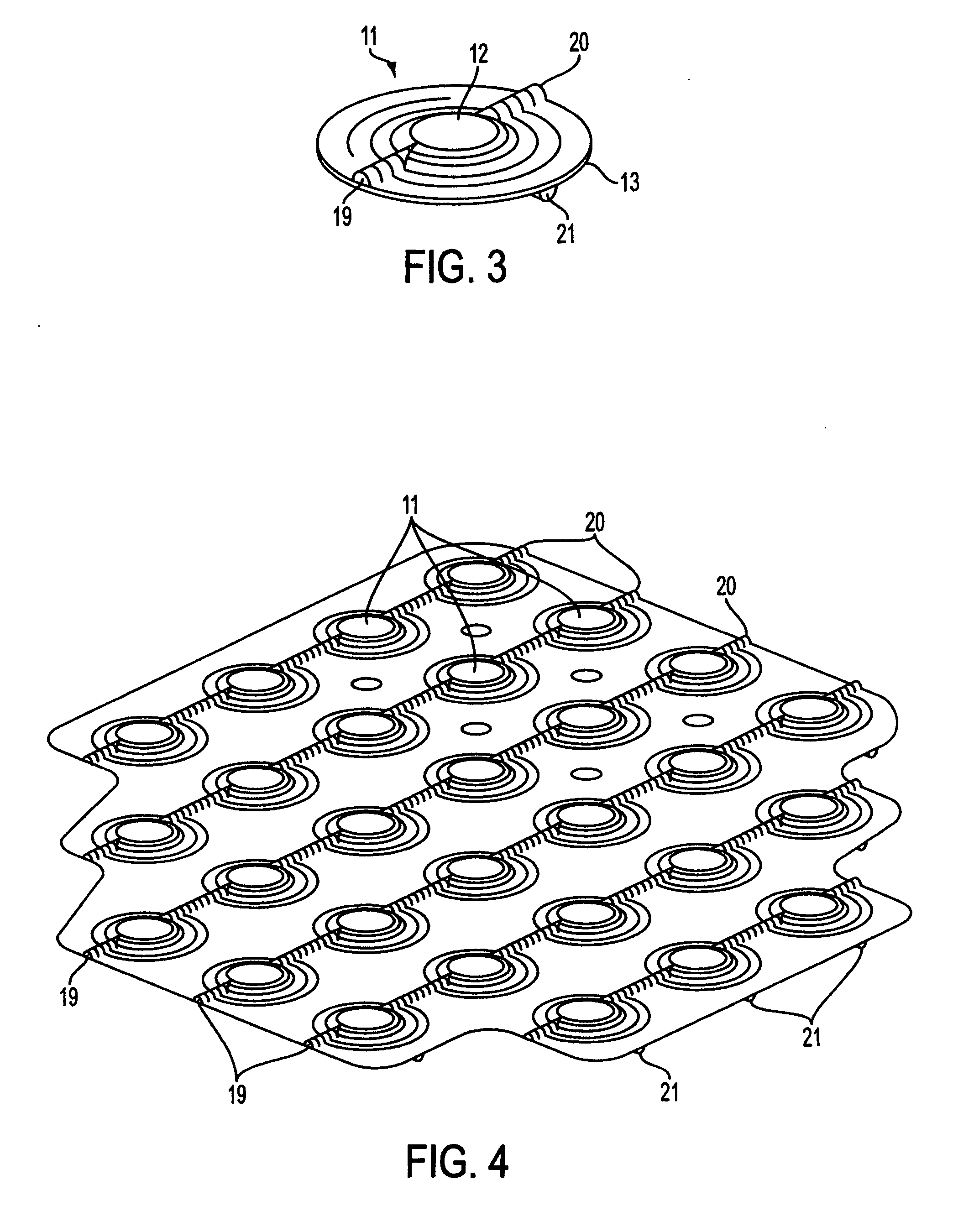
[0018] The parts indicated on the drawings by numerals are identified below to aid in the reader's understanding of the present invention. [0019]11. Pneumatic stimulating node. [0020]12. Upper layer. [0021]13. Diaphragm layer. [0022]14. Upper cavity. [0023]15. Lower layer. [0024]16. Lower cavity. [0025]17. Valve stem. [0026]18. Vavle seat. [0027]19. Upper cavity air line. [0028]20. Upper cavity air line. [0029]21. Lower cavity air line.

[0030]FIG. 1 shows a cross sectional view of an embodiment of a single pneumatic stimulating node of the instant invention in the non-operated state. In FIG. 1, 11 indicates the pneumatic stimulating node generally, 12 indicates the upper layer of the pneumatic stimulating node, and 13 indicates the diaphragm layer of the stimulating node. The upper cavity, 14, of the pneumatic stimulating node, 11, may be pressurized with an air line not shown in this figure. The lower layer, 15, of pneumatic stimulating node, 11, and the diaphragm layer, 13, enclos...


PUM


Abstract

An array of pneumatic stimulating nodes with integral pneumatically operable ANDing is disclosed. These stimulating nodes may be used to convey spatial orientation information to an individual in an attitudinally ambiguous situation via direct stimulation of his skin. The stimulating nodes of the instant invention may be arranged orthogonally in an array if this is convenient, or in a wide range of other configurations. The pneumatic stimulating nodes of the invention are comprised of three layers, and upper layer, diaphragm layer, and a lower layer which may be separately injection molded from suitable materials, for example, urethane thermoplastic elastomer, and fused together using radio-frequency welding techniques to form the complete stimulating array.

Description

BACKGROUND OF THE INVENTION [0001] 1. Field of Invention [0002] This invention relates to stimulus arrays, more particularly to tough and resilient pneumatic stimulus arrays that may be developed proximal to the skin of a use, and that may be manufactured cheaply with minimum number of operations. [0003] 2. Description of the Related Art [0004] Recently, the U.S. Naval Aerospace Medical Research Laboratory (NAMRL) at Pensacola, Fla., demonstrated complete and reliable control of aircraft attitude by a pilot flying with a blindfold in place. This was a remarkable feat, especially when it is remembered that not even a goose will fly blind in a fog. Geese released in a cloud will extend their wings upward so that their body becomes a pendulous gravity sensor and fall feet-first until they either land or clear the cloud. Attitude control was achieved by the NAMRL pilot by appraising him of his spatial orientation with an array of stimulators arranged about his torso. These stimulators w...

Claims


Application Information

Patent Timeline
IPC IPC(8): A61HA61H23/04
CPCA61H2201/0134A61H23/04
Inventor CUSHMAN, WILLIAM B.
Owner HEMBY JR JOSEPH K
Why Eureka
Try Eureka