Leaf stripper, more particularly designed for selective vine leaf stripping

a leaf stripper and leaf technology, which is applied in the field of leaf strippers, can solve the problems of inability to apply frictional contact rollers to separate leaves, inability to arrange mechanical instruments in vegetation layers, and inability to apply leaf stripping using frictional contact rollers, so as to avoid leaf tearing or crumbling.

Inactive Publication Date: 2005-04-21
PELLENC SA
View PDF1 Cites 21 Cited by
  • Summary
  • Abstract
  • Description
  • Claims
  • Application Information

AI Technical Summary

Benefits of technology

[0043] This supplementary pulling mechanism has the advantageous function of pulling in even more leaves and keeping them pinned against the lateral opened surface of the drum, so that they do not come out again.
[0044] Using this device, the leaves pinned against the drum are pulled in the direction of rotation of the drum and during this movement, the petioles of the leaves ar...

Problems solved by technology

Leaf stripping thus turns out to be an operation that is very much of interest and that corresponds well to the problem of optimization of tasks and the pursuit of quality of the harvest.
The failure of this machine results certainly from the fact that the principle of separating the leaves using frictional contact rollers does not appear to be able to be applied concretely for several reasons.
Following the description and the drawings of document FR-2,417,932, the articulated supports mounted on springs carrying the contact rollers are assigned to be arranged, during work, in the vegetation layer; this arrangement can not be applied due to the fact that these supports rub in the vegetation layer and hinder the aspiration of the leaves because they push back the vegetation; it is not possible to arrange the mechanical instruments in the vegetation layer beyond the wall of the rotary cage, since they would collide with and be torn off by various obstacles located in the axis of the vine row, such as stakes, guy wires, and above all, poles.
Due to the fa...

Method used


Image

  • Leaf stripper, more particularly designed for selective vine leaf stripping
  • Leaf stripper, more particularly designed for selective vine leaf stripping
  • Leaf stripper, more particularly designed for selective vine leaf stripping

Examples


Embodiment Construction

[0067] Reference is made to the drawings to describe an advantageous embodiment example, though in no way restrictive, of the leaf stripping machine according to the invention.

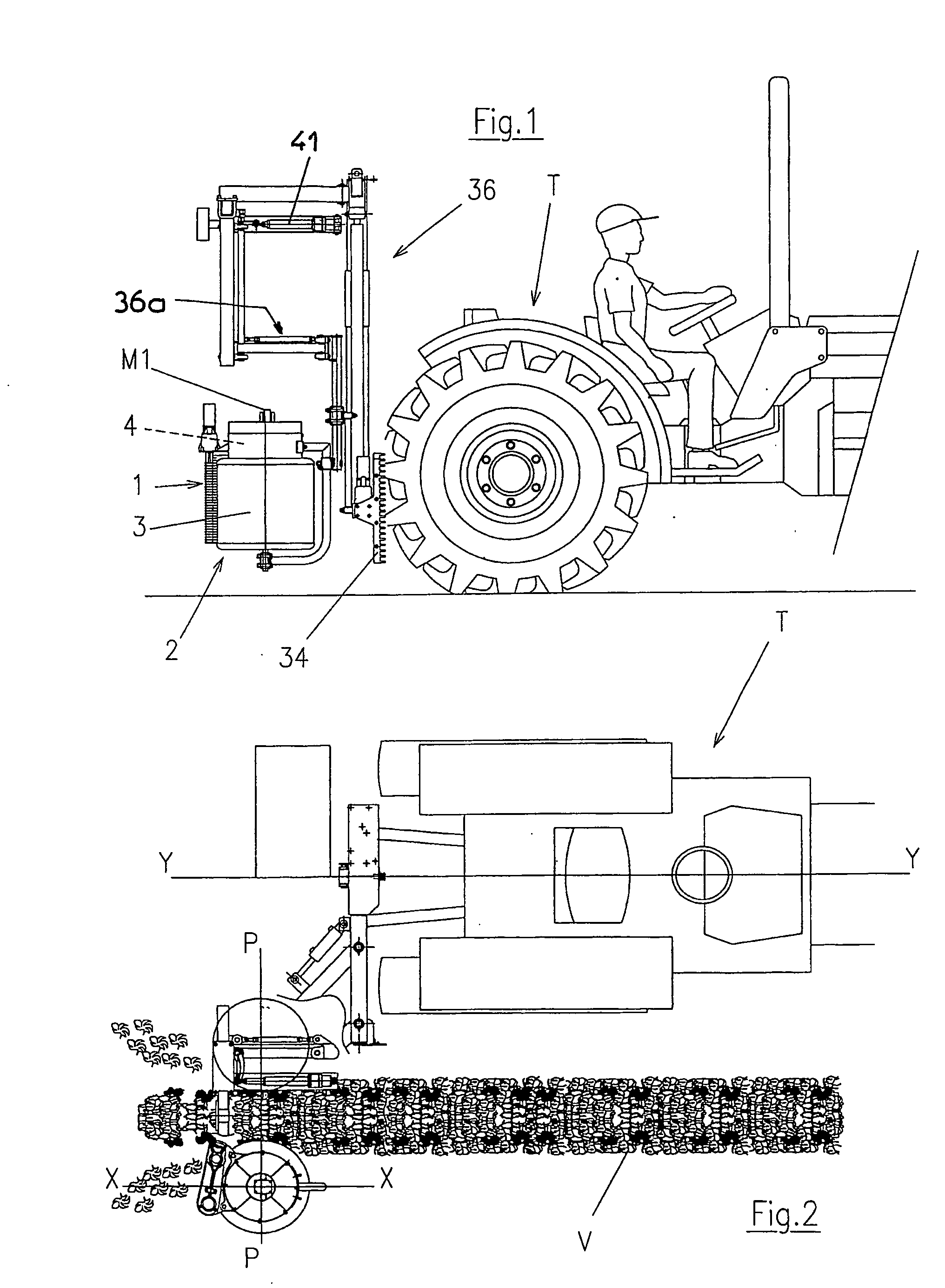
[0068] Though reference is made, in the following portion of the present document, solely to the use of this leaf stripping machine in order to make a leaf stripping machine specifically for the vine, it is obvious that such a usage is not restrictive and that this machine can be used in order to perform leaf stripping of other plants cultivated in the form of aligned shrubs.

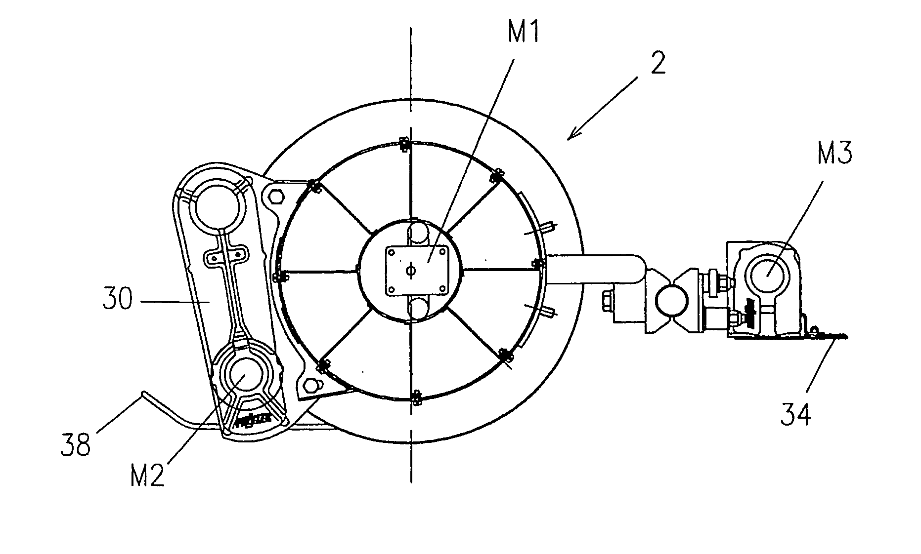
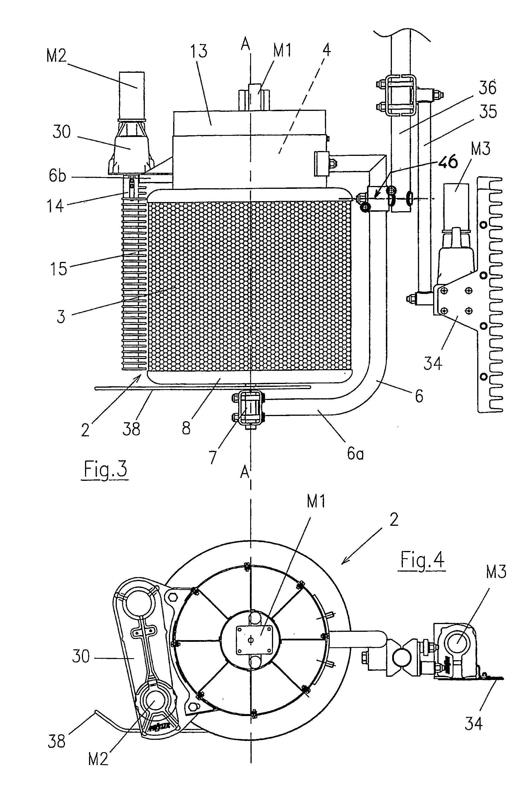
[0069] This leaf stripping machine is of the type described in the document FR-2,808,964 A. It consists of at least one leaf stripping head or module 1 comprising a rotary aspirating drum 2 consisting of an opened cylindrical wall 3. In a preferred manner, the leaf stripping machine consists of two leaf stripping heads or modules 1 designed to be placed on both sides of the vegetation of the vine row, during work, in a manner so as to fi...


PUM


Abstract

The invention relates to a leaf stripper which is intended more specifically for stripping vine leaves. The inventive leaf stripper consists of a stripping head (1) which is equipped with a rotary drum comprising an open-work cylindrical side wall (3), means of rotating said drum, suction means (4) which can be used to generate a suction air stream that passes through the aforementioned open-work cylindrical side wall (3) of the drum, a means of channeling the air stream through a portion modifying the side wall and a cutting means (14) which is installed close to the side wall portion of the rotating suction drum and which is positioned parallel or essentially parallel to the axis of rotation (A-A) of the drum. The invention is characterized in that the open-work cylindrical wall (3) of the drum (2) is made from a flexible, deformable material which is permeable to the air stream.

Description

RELATED U.S. APPLICATIONS [0001] Not applicable. STATEMENT REGARDING FEDERALLY SPONSORED RESEARCH OR DEVELOPMENT [0002] Not applicable. REFERENCE TO MICROFICHE APPENDIX [0003] Not applicable. FIELD OF THE INVENTION [0004] The invention involves a leaf stripping machine specifically designed for selective leaf stripping of a vine. BACKGROUND OF THE INVENTION [0005] Leaf stripping is a technique that consists in eliminating a more or less sizeable quantity of leaves located in the fructiferous zone of plants. Done manually for a long time in some vineyards, this operation, which aims to improve the quality of the harvest and to make easier the manual work of thinning and picking, is experiencing a growing interest with the development of mechanical leaf stripping. [0006] The interests in leaf stripping are manifold: [0007] Promote the aeration of bunches of grapes in order to reduce rot; [0008] Promote thinning in order to improve the coloration (thicker grape skin); [0009] Thin out t...

Claims


Application Information

Patent Timeline
IPC IPC(8): A01G17/02
CPCA01G17/02A01G17/026
Inventor PELLENC, ROGER
Owner PELLENC SA
Why Eureka
Try Eureka