Cooling device and electronic apparatus building in the same

a cooling device and electronic equipment technology, applied in domestic cooling devices, containers, instruments, etc., can solve the problems of large cost reduction and difficulty in achieving the cooling of parts, and achieve the effect of low cost and high density of liquid cooling devices

Inactive Publication Date: 2005-04-21
HITACHI LTD
View PDF11 Cites 58 Cited by
  • Summary
  • Abstract
  • Description
  • Claims
  • Application Information

AI Technical Summary

Benefits of technology

[0016] An object is, according to the present invention, therefore to provide a liquid cooling device, being installable with high density

Problems solved by technology

As was disclosed in the patent document 1, high-performances and high-density for installation of an electronic apparatus advances in recent years, and then accompanying with this, it is difficult to achieve the cooling upon the parts thereof,

Method used


Image

  • Cooling device and electronic apparatus building in the same
  • Cooling device and electronic apparatus building in the same
  • Cooling device and electronic apparatus building in the same

Examples


example 1

[0038] Hereinafter, explanation will be given on the details of the embodiment 1, according to the present invention, by referring to the drawings attached.

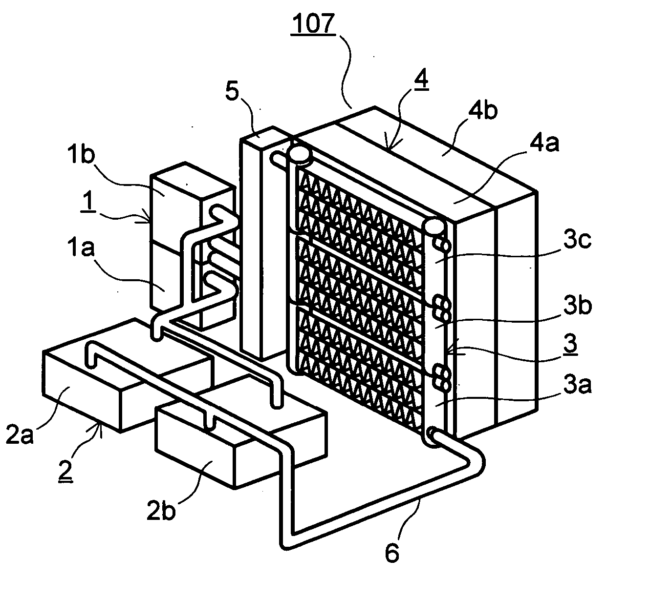
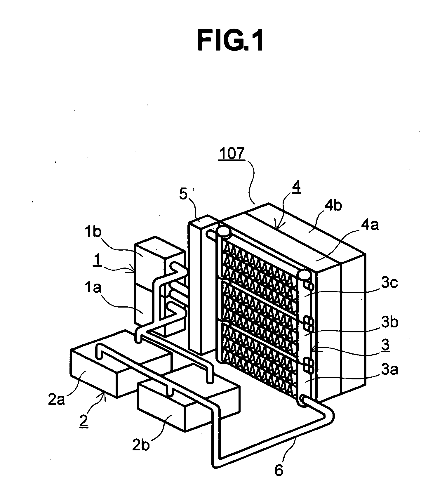
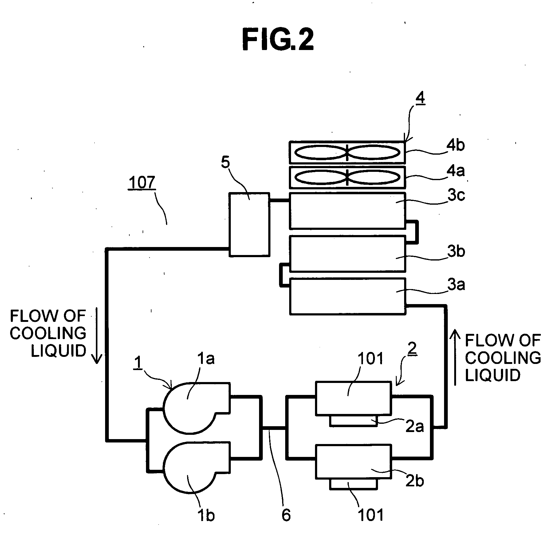
[0039] First, as the first embodiment of the present invention, there is shown a liquid cooling device, to be installed into a server of the 2CPU structure having a housing height of 3U (about 133 mm). FIG. 1 is a view for showing an outlook of the present liquid cooling device 107. FIG. 2 is a block diagram of the present liquid cooling device. FIG. 3 is a view for showing an outlook of a lack housing of the server of the lack-mount thereof, into which the present liquid cooling device 107 is installed.

[0040] The present liquid cooling device is built up with two (2) sets of pumps 1 (1a and 1b), liquid cooling jackets 2 (2a and 2b) for absorbing the heat generated from CPUs into the cooling liquid, each being provided for one CPU, i.e., two (2) pieces in total thereof, three (3) pieces of radiators 3 (3a, 3b, and 3c) for radia...

embodiment 2

[0051] Next, as a second embodiment of the present invention, an outlook of the liquid cooling device, to be installed into the server of the 2CPU structure having the 1U (about 44 mm) height of the housing. The same reference numerals are attached with, for the structures same or similar to those shown in the embodiment 1, therefore the explanation thereon will not be repeated herein. It is also true to other embodiments. This FIG. 4 is a view for showing an outlook of the present liquid cooling device 108, and it is constructed with assumption that it is installed into the server having the 1U height as shown in FIG. 11 mentioned above, for example. The heights of the pump 1, the liquid cooling jacket 2, the unitary radiator 3d, 3e, and the reservoir 5 are set to be within the 1U height. As is shown in the figure, the unitary radiators 3d and 3e are disposed in the horizontal direction, juxtaposing with. In this case, the horizontal direction means the forward direction with respe...

example 3

[0056]FIG. 6 shows an example of the structure, in a case where two (2) sets of the unitary radiators shown in FIG. 5 mentioned above, being combined with each other, are installed, aligning in series in a direction on a plan, and it is the structure being applicable into the liquid cooling system for use in the server of the 1U height, shown as the second embodiment in the above, for example. In this example, the unitary radiators are combined with in the horizontal direction, and in this case, the horizontal direction means the direction, being orthogonal (90°) to the ventilation direction. In this combination, sealing caps 16 (16a and 16b) are out on the connectors, on which the connection is unnecessary, and the liquid conduits 6 are connected only to the necessary connectors 14b and 14c′. Thus, the connectors 14d, 14b′: 14c, 14a between the unitary radiators 3e and 3f are connected with, respectively.


PUM


Abstract

In a liquid cooling system of low costs and being installable with high density into a server having a several kinds of predetermined heights of housings, each of devices building up the liquid cooling system is set to be within about 44 mm, being the standard height of a lack when installing into a cabinet for the server lack of lack-mount method, in particular, about from 40 mm to 36 mm, and this is combined with, thereby building up a liquid cooling system of low costs and enabling high density installation, for an electronic apparatus of lack-mount method having different heights.

Description

BACKGROUND OF THE INVENTION [0001] The present invention relates to an electronic apparatus, including an electronic computer therein, and in particular, to a liquid cooling device, being applicable into cooling of an information processing apparatus, such as, a server of lack-mount type, thereby enabling to obtain high-performances and small-sizing for such the apparatus. [0002] In the system configuration, space for storage and installation of an information processing apparatus, such as a server, etc., so-called a lack-mount method or type comes to be a main current in recent years. This lack-mount method is a method of installing a housing, being so-called a “lack”, for storing the apparatus therein, by stacking, while being divided, into the function units, separately in a unit chassis, being so-called a “cabinet”, which is formed or manufactured in accordance with a specific regulation or standard thereof. With such the lack-mount method, there can be obtained advantages that ...

Claims


Application Information

Patent Timeline
IPC IPC(8): F25D9/00F28D1/053F28D15/02F28F9/02F28F9/26G06F1/20H01L23/473H05K7/00H05K7/20
CPCF28D1/05366F28D2021/0031F28F9/262H01L23/473H01L2924/0002F28D15/00H01L2924/00G06F1/20
Inventor SUZUKI, OSAMUOHASHI, SHIGEOMATSUSHIMA, HITOSHIMATSUSHITA, SHINJIASANO, ICHIROUMINAMITANI, RINTARO
Owner HITACHI LTD
Why Eureka
Try Eureka