
Twist-extrusion process

a technology of twisting and extrusion, which is applied in the direction of metal extrusion, metal rolling arrangement, manufacturing tools, etc., can solve the problems of high product cost, high labor intensity, low productivity and degradation of material structure and properties, and achieve high strain

Inactive Publication Date: 2005-04-21
ENGINEERED PERFORMANCE MATERIALS
View PDF7 Cites 36 Cited by
  • Summary
  • Abstract
  • Description
  • Claims
  • Application Information

AI Technical Summary

Benefits of technology

"The invention is a method of severe plastic deformation to create high strains during one step processing for structure refinement. The method involves using a shear-extrusion method to form long products of different shapes simultaneously. The method involves steps such as providing cylindrical billets, preheating, placing in a container of the extrusion tool, forcing through an extrusion die, controlling extrusion and angular speeds, and repeating the process for subsequent billets. The method can be used with various materials such as aluminum alloys, magnesium alloys, titanium alloys, powders, and composites. The method also includes controlling the billet preheating temperature and extrusion speed to achieve the desired strain and temperature during the extrusion process. The invention also includes tools for forward and backward shear-extrusion, a die for shear-extrusion, and a portal die for shear-extrusion of hollow shapes. The technical effects of the invention include achieving high strains during structure refinement, simultaneous formation of long products of different shapes, and improved quality of the refined structure."

Problems solved by technology

In result, such processing is time and labor consuming with a high product cost.
In most cases, their conversion to final products presents additional problems with the increase in the cost.
However, the only known method in the art for such products is superplastic extrusion (see U.S. Pat. No. 5,620,537).
The second step should be realized with very low strain rates or high temperatures that leads to low productivity and degradation of the material structure and properties.
Therefore, the known method does not provide evident technical benefits and did not find practical applications.

Method used


Image

  • Twist-extrusion process
  • Twist-extrusion process
  • Twist-extrusion process

Examples


Embodiment Construction

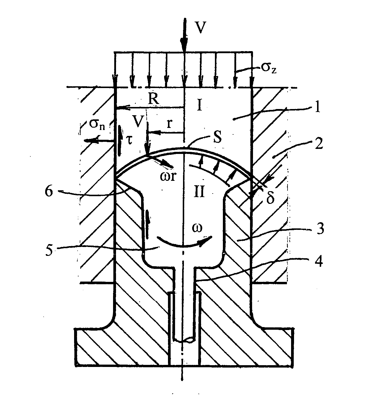
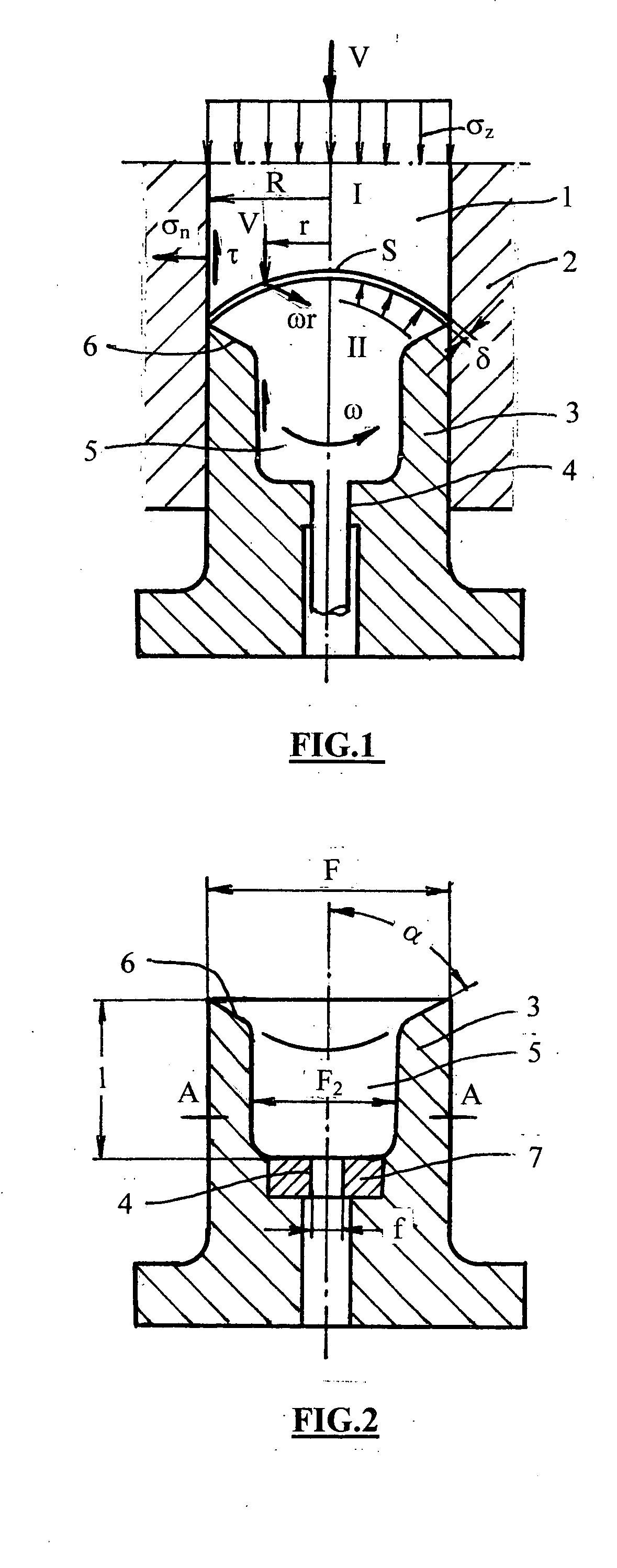
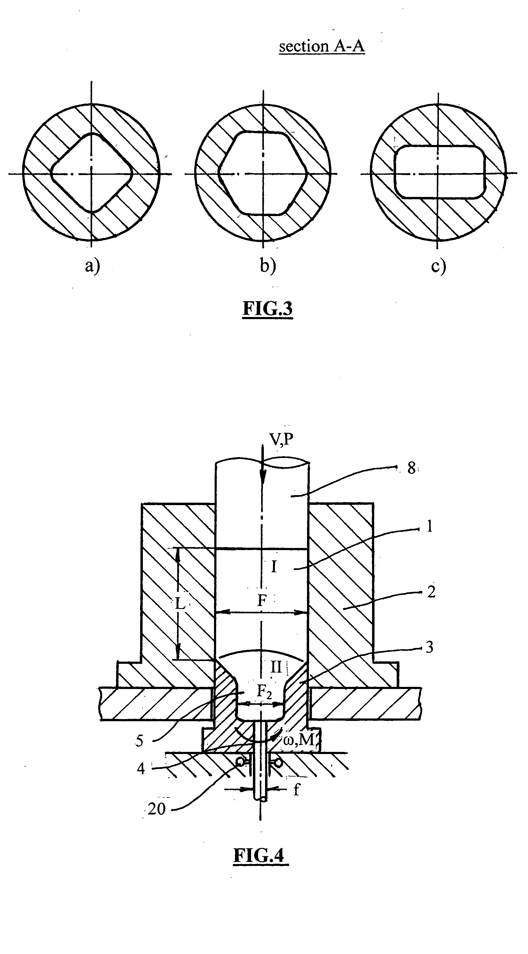
[0021] Now, the invention will be described in details with reference to accompanying figures. FIG. 1 shows the principle of the shear-extrusion process. Similarly to ordinary extrusion, a cylindrical billet 1 is placed into a container 2 of the extrusion tool. The billet 1 is forced for extruding from the container 2 through a die 3 under action of stresses σz applied by a press (does not shown) moving with an extrusion speed V. The extrusion die 3 is provided with an outlet orifice 4 which defines the extruded product. In contrast to known methods, the die 3 comprises an intermediate extrusion chamber 5 with a cone 6 and is rotated with an angular speed ω relative to the container 2 by an additional mechanism (does not shown). The chamber 5 has non-circular cross-sections of the sufficient length l. The transition cone 6 prevents the penetration of oxides, lubricants and other surface contaminations inside the extruded product. Details of the extrusion die are shown in FIG. 2. The...


PUM

PropertyMeasurementUnit
temperatureaaaaaaaaaa
areaaaaaaaaaaa
extrusion speedaaaaaaaaaa

Abstract

A shear-extrusion method of severe plastic deformation for fabrication of metal shapes with ultra-fine structures is described. The improvements of the method include unidirectional shear of any required intensity during one step processing and under high hydrostatic pressures, fabrication of long products with different cross-sections, refinement of low ductile alloys, the increase of productivity and cost reduction. The method can be realized as forward extrusion, backward extrusion, semi continuous extrusion and extrusion of hollow shapes in portal dies with a welding chamber.

Description

BACKGROUND OF THE INVENTION [0001] 1. Field of the invention [0002] The present invention relates to severe plastic deformation of metals and alloys to control their structure and properties. [0003] 2. Description of the Prior Art [0004] It is known in the art that severe plastic deformation performed by simple shear results in refinement of grain structures to the sub-micron, sometimes to nano scale. That leads to significant improvements in many physical and mechanical properties such as strength, ductility, fatigue, corrosion resistance, super plasticity, etc. Different processing methods were developed for intensive plastic deformation. Most of them are restricted by small sample sizes or soft materials and are used as a laboratory tool: high pressure torsion (P. W. Bridgeman, Studies in Large Plastic Flow and Fracture, McGrill, New York, 1952), cyclic extrusion-compression (A. Korbel, M. Richert, J. Richert, in: Second RISO International Symposium on Metallurgical Science, 1981...

Claims


Application Information

Patent Timeline
Patent Type & Authority Applications(United States)
IPC IPC(8): B21C23/01
CPCB21C23/01B21C23/001
Inventor SEGAL, VLADIMIR M.
Owner ENGINEERED PERFORMANCE MATERIALS
Learn More