Method of manufacturing cylinder head

a manufacturing method and cylinder head technology, applied in the field of manufacturing cylinder heads, can solve problems such as adverse effects on the core, and achieve the effect of minimizing the thermal effects of molten metal

Inactive Publication Date: 2005-04-21
NISSAN MOTOR CO LTD
View PDF3 Cites 11 Cited by
  • Summary
  • Abstract
  • Description
  • Claims
  • Application Information

AI Technical Summary

Benefits of technology

[0010] The present invention has been completed upon such studies conducted by the present inventor and has an object to provide a method of manufacturing a cylinder head wherein even when a partition plate with a thinned wall is preliminarily set in a casting mold to allow the partition plate to be cast in with molten metal for cast molding, thermal affects resulting from molten metal can be minimized as less as possible for thereby performing smooth cast molding.

Problems solved by technology

During such cast-in formation, a big difference occurs in coefficient of thermal expansion between the partition plate and the core that holds this partition plate, and it is conceived that the partition plate thermally expands due to heat of molten metal to adversely affect the core with a resultant formation of burrs in the cylinder head.

Method used


Image

  • Method of manufacturing cylinder head
  • Method of manufacturing cylinder head
  • Method of manufacturing cylinder head

Examples


first embodiment

[0032] A first embodiment according to the present invention is described below.

[0033] First, a cylinder head 1 with a partition plate 10 for an intake port 4 is described.

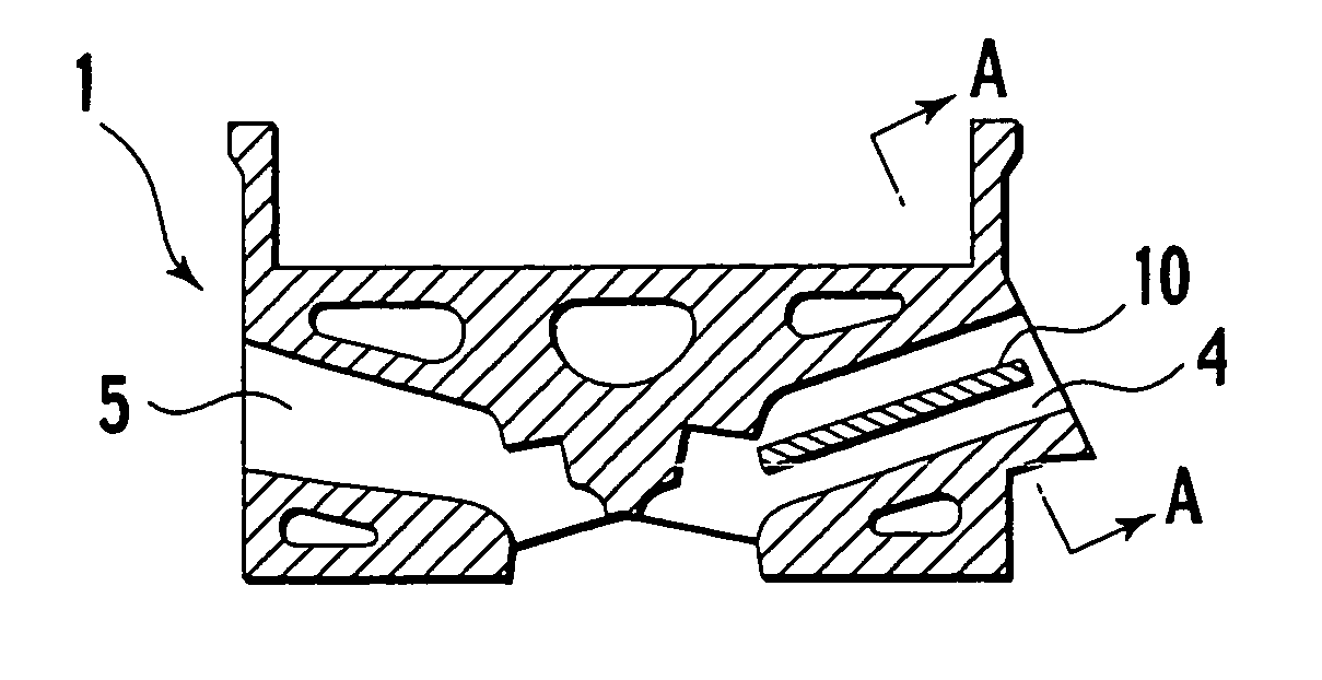
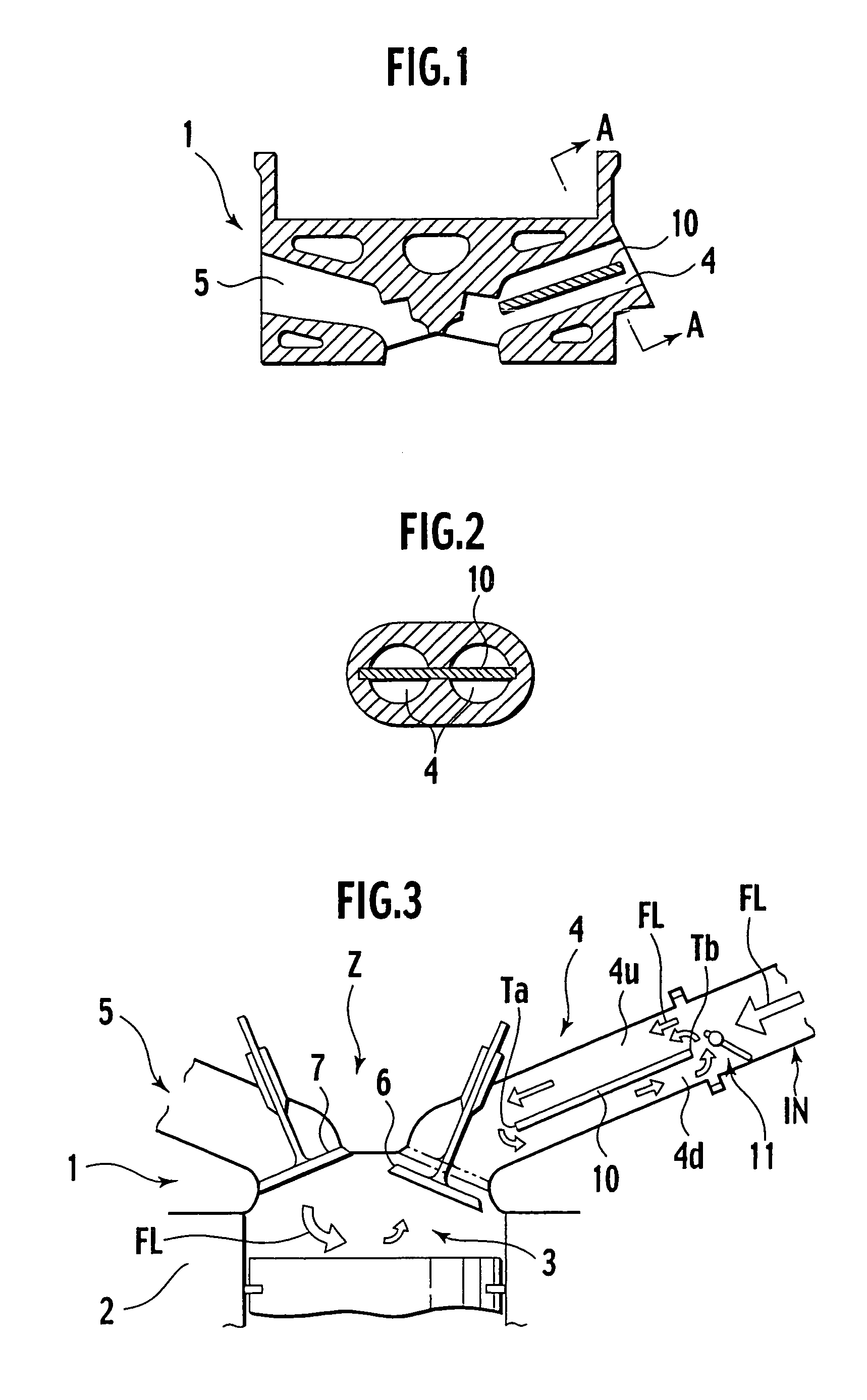
[0034]FIG. 1 is a schematic cross sectional view illustrating a cylinder head 1, of an engine, of the presently filed embodiment; FIG. 2 is a cross sectional view taken on an orthogonal plane of an intake port 4 of the cylinder head 1 and corresponds to a cross sectional view taken on line A-A in FIG. 1; FIG. 3 is a schematic view illustrating a flow current condition in the cylinder head 1; and FIG. 4 is a schematic plan view of the cylinder head shown in FIG. 3.

[0035] As shown in FIGS. 1 to 3, the cylinder head 1 is set on a top of a cylinder block 2 and has the intake port 4 for introducing intake airflow, composed of air and fuel gas delivered from an intake manifold IN, into a cylinder bore 3 and an exhaust port 5 through which exhaust gases resulting from combustion in the cylinder bore 3 are exhausted. I...

second embodiment

[0068] A second embodiment according to the present invention is described below.

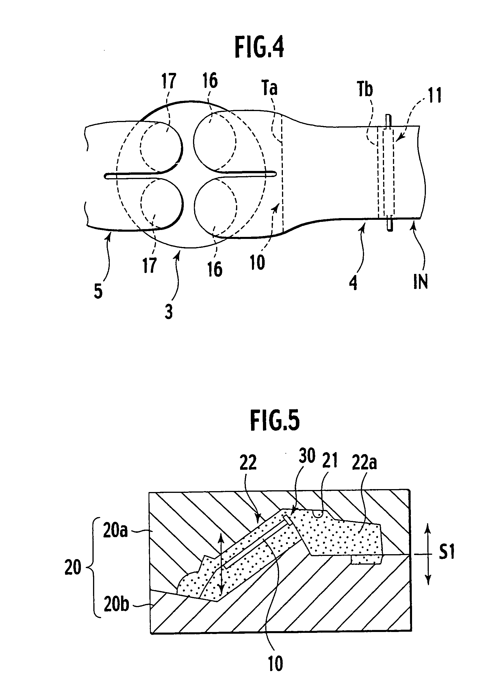
[0069]FIG. 14 is a schematic plan view illustrating a structure wherein a plate member of the presently filed embodiment is located at an end of a partition plate; FIG. 15 is a schematic cross sectional view taken on line E-E of FIG. 14; and FIG. 16 is an enlarged view of an essential part of FIG. 15.

[0070] As shown in FIGS. 14 to 16, expansion-permit spaces 30 of the presently filed embodiment are formed using a plate member 32, with a U-shaped configuration in cross section, which covers the intake-side distal end Tb of the partition plate 10.

[0071] When forming the core 22 under a condition where the partition plate 10 is preliminarily placed in the core mold 20 as shown in FIG. 15, the plate member 32 is placed on the circumferential edge of the cavity 21 of the core mold 20 under a condition where a body section 32b engages the partition plate 10 in a way to allow a U-shaped bottom wall 32a to b...

third embodiment

[0079] A third embodiment according to the present invention is described below.

[0080]FIG. 18 is a schematic cross sectional view illustrating a structure in which an insert, having a thermal solubility, of the presently filed embodiment according to the present invention is placed in a core.

[0081] With the presently filed embodiment, the expansion-permit space 30 is formed using a thermally soluble insert 33 and the insert 33 is disposed in the core 22 in contact with the intake-side distal end Tb of the partition plate 10.

[0082] An example of the thermally soluble insert 33 may include wax, styrene foam and various plastic foams.

[0083] As shown in FIG. 18, pouring molten metal to the intake-side distal end Tb of the partition plate 10 disposed in the core 22 with the core 22 containing the thermally soluble insert 33 allows the thermally soluble insert 33 to be melt with heat of molten metal, thereby forming given spaces 30 with no presence of mold sand in the core 22. Consequ...


PUM

PropertyMeasurementUnit
thicknessaaaaaaaaaa
thicknessaaaaaaaaaa
lengthaaaaaaaaaa

Abstract

In a method of manufacturing a cylinder head having a partition plate for an intake port, there is prepared a partition plate having an intake-side distal end and a cylinder-side distal end. The partition plate is located in a core to form the intake port and molten metal is supplied to a periphery of the partition plate. After solidifying the molten metal, the core is removed. At least the intake-side distal end of the partition plate is located in an expansion-permit space that permits thermal expansion of the partition plate caused by heat of molten metal.

Description

BACKGROUND OF THE INVENTION [0001] The present invention relates to a method of manufacturing a cylinder head and, more particularly, to a method of manufacturing a cylinder head with an intake port in which a partition plate is disposed. [0002] In recent years, a cylinder of an internal combustion engine includes a cylinder head is formed with an intake port in which a partition plate, called as a tumble plate, is incorporated. [0003] Japanese Patent Application Laid-Open Publication No. 2001-193469 (see paragraphs 0011, 0020 and 0022 and FIGS. 1, 3 and 4) and Japanese Patent Application National Publication of Translated Version No. 2002-501829 (see paragraph 0022 and FIG. 3) disclose structures wherein an airflow control valve disposed in an intake-side distal end of an intake port is controlled while permitting a partition plate to deflect intake air, introduced from the intake port to a cylinder bore, for intensifying tumble flow occurring inside the cylinder bore to achieve im...

Claims


Application Information

Patent Timeline
Patent Type & Authority Applications(United States)
IPC IPC(8): B22C9/10B22C9/24B22D19/00B22D19/08F02F1/24
CPCB22C9/10B22D19/0009F02B31/085F02B2275/48Y02T10/146F02F1/4242F02F2200/06Y02T10/125F02F1/24Y02T10/12
Inventor AKABA, KONOMI
Owner NISSAN MOTOR CO LTD
Why Eureka
Try Eureka