Shielded encapsulated vacuum interrupter

a vacuum interrupter and shielding technology, applied in the direction of air-break switches, switchgear arrangements, high-tension/heavy-dress switches, etc., can solve the problems of affecting the performance of the system, affecting the operation and maintenance of the system, and affecting the safety of personnel

Inactive Publication Date: 2005-04-21
G & W ELECTRIC
View PDF13 Cites 31 Cited by
  • Summary
  • Abstract
  • Description
  • Claims
  • Application Information

AI Technical Summary

Problems solved by technology

Underground systems pose new operational and maintenance challenges by virtue of being largely unseen.
However, at times, personnel safety may conflict with system performance.
However, if the switch is grounded, the electric fields inside the device become distorted and reduce the dielectric withstand capability of the open gap during a switch “break” operation.
Mitigation of this electric field distortion has so far been elusive to those knowledgeable in the art.
Bohme et al. recognize that the space is susceptible to capacitive discharge due to breakdown of the insulating material (e

Method used


Image

  • Shielded encapsulated vacuum interrupter
  • Shielded encapsulated vacuum interrupter
  • Shielded encapsulated vacuum interrupter

Examples


Embodiment Construction

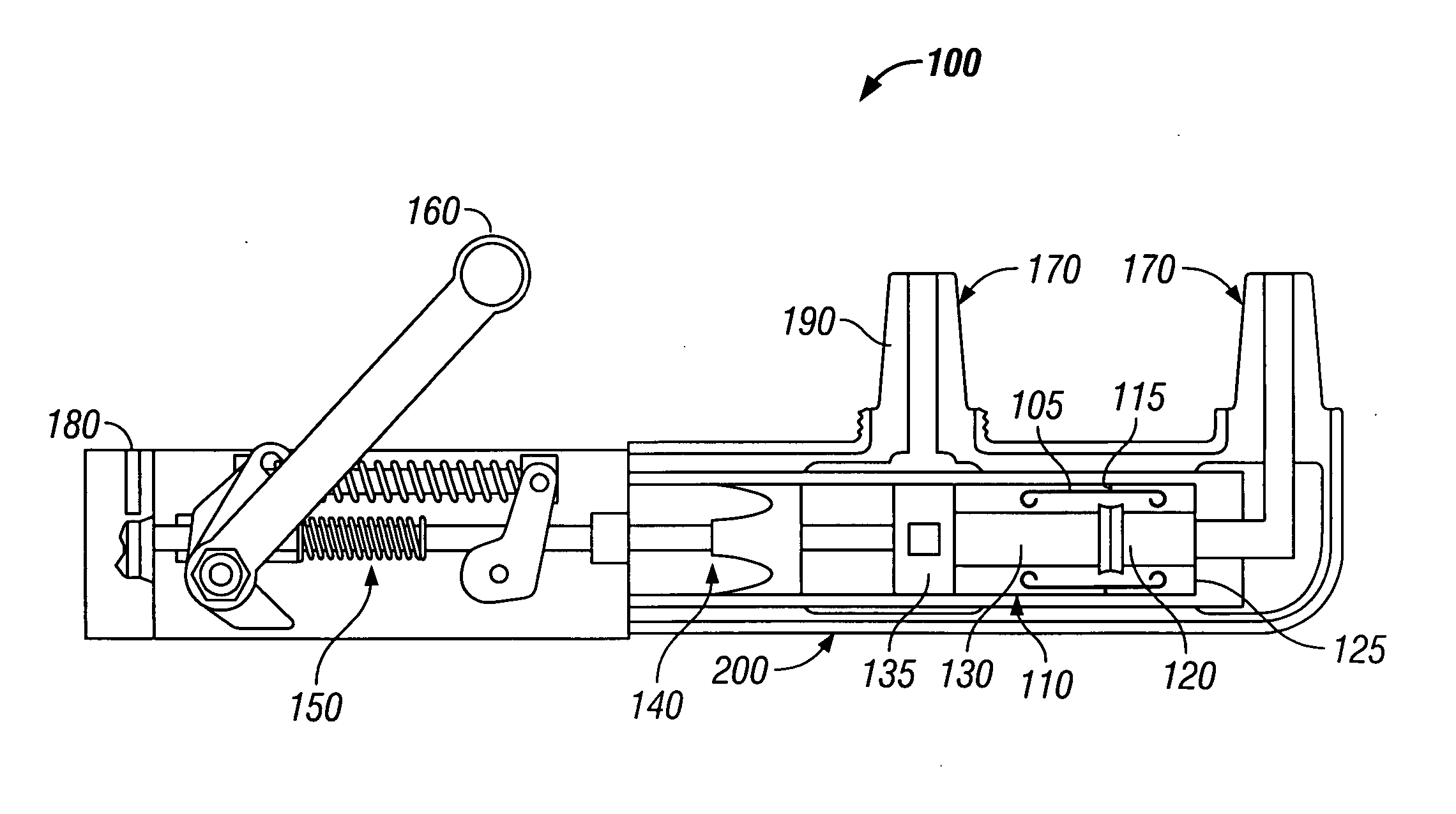
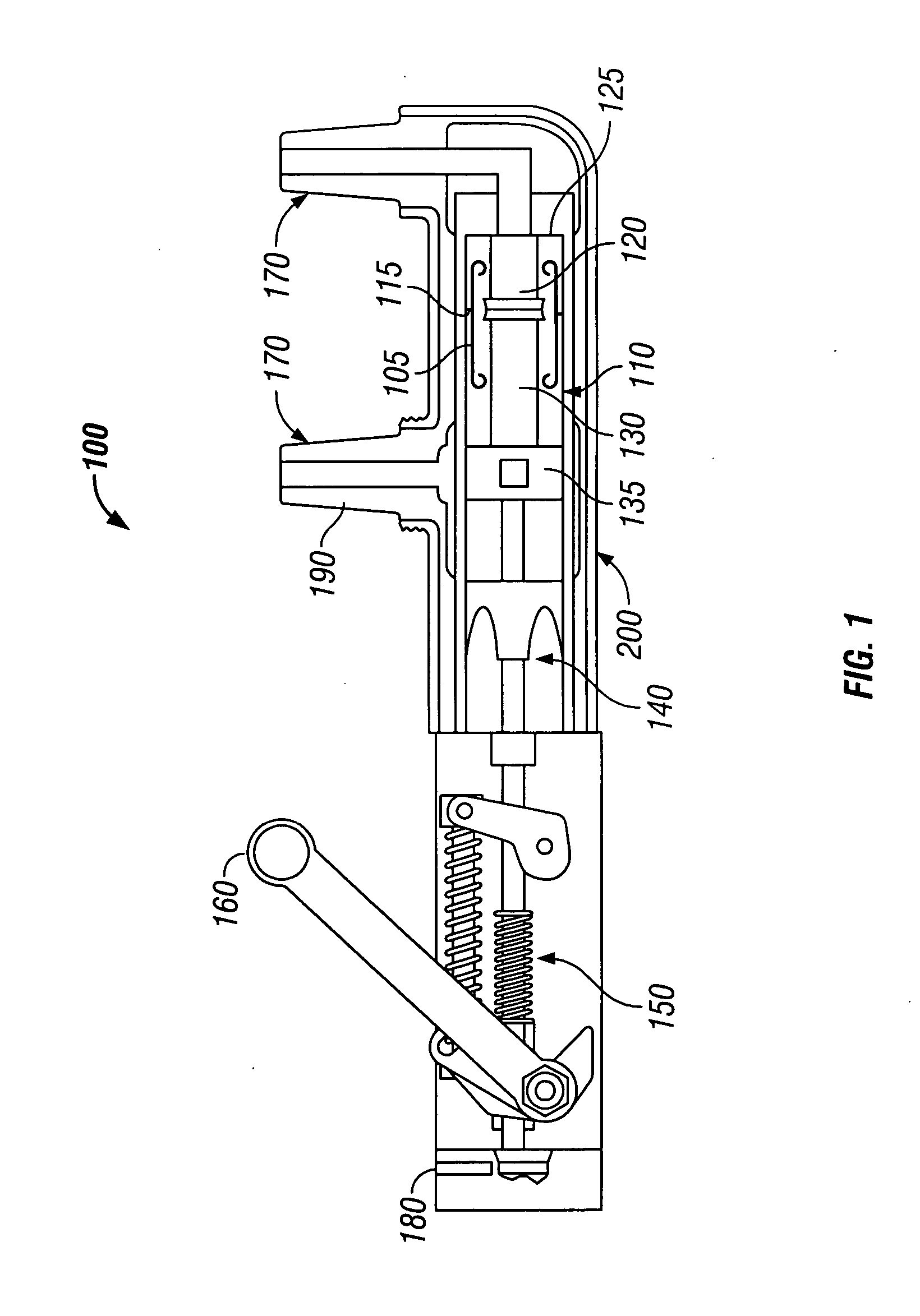
[0016] Referring now to the drawings, FIG. 1 shows a cross-sectional view of the internal component arrangement of an exemplary vacuum interrupter 100. Vacuum interrupter 100 may be employed in a power distribution system to open or close an electric circuit. Current flow through the interrupter 100 may be interrupted or restored by vacuum chamber 110. Vacuum chamber 110 includes a generally cylindrical-shaped ceramic housing and two conductive end caps which seal the vacuum chamber and maintain a vacuum therein. Referring to FIG. 1, the vacuum chamber 110 has a “fixed” end and a “movable” end. A fixed contact 120 is disposed within the fixed end of vacuum chamber 110 and is in contact with conductive fixed end cap 125. A movable contact 130 is disposed within the movable end of vacuum chamber 110 and is coaxially aligned with fixed contact 120. Movable contact 130 is in electrical contact with end cap 135 and coaxially engages and disengages from fixed contact 120 to make or break ...


PUM


Abstract

A shielded encapsulated vacuum interrupter with a ceramic vacuum chamber and opposing conductive end caps is provided. One end cap is electrically connected to a fixed contact, while an opposing end cap is connected to a moving contact. The moving contact is actuatable with the fixed contact for opening or closing an electric circuit. A floating shield inside the vacuum chamber connected to the vacuum chamber ceramic wall and spaced from the fixed and moving contacts is isolated and has a floating voltage potential. A portion of the vacuum chamber exterior ceramic wall is coated with a semi-conductive material and conductive voltage screens enclose a portion of the vacuum chamber exterior and are electrically connected to each conductive end cap of the vacuum chamber. The chamber and connected screens are encapsulated in a molded dielectric housing.

Description

FIELD OF THE INVENTION [0001] The present invention pertains to current interrupting devices for power distribution systems. More particularly, the present invention relates to encapsulated vacuum interrupting devices for shielded power distribution systems. BACKGROUND OF THE INVENTION [0002] Now more than ever, electric utility power distribution systems are being constructed underground due to public outcry about esthetics of aerial (i.e., above-ground) distribution systems in what is now known as the Not In My Backyard (NIMBY) phenomenon. To appease the NIMBY contingent, power distribution systems formerly constructed of poles, wires, and pole-mounted switches and transformers are being superceded and even replaced by underground systems constructed of conduits or duct-banks, underground vaults, cables, and ground level or sub-ground level switchgear and transformers. Underground systems pose new operational and maintenance challenges by virtue of being largely unseen. In respons...

Claims


Application Information

Patent Timeline
IPC IPC(8): H01H3/00H01H33/02H01H33/66H01H33/662
CPCH01H33/027H01H33/66261H01H2033/66284H01H2033/6623H01H33/666H01H33/662H02B13/0354H01H2033/66269H01H2033/66292H01H2239/044
Inventor MARTIN, DONALD R.
Owner G & W ELECTRIC
Why Eureka
Try Eureka