
Flying vehicle-launching apparatus and method

a technology for flying vehicles and apparatuses, applied in the direction of launching/towing gear, cosmonautic vehicles, transportation and packaging, etc., can solve the problems of difficult to smoothly accelerate spacecraft, difficult to reuse fuselage, and risk of carriage derailment, so as to achieve safe and efficient acceleration

Inactive Publication Date: 2005-04-21
CENTRAL JAPAN RAILWAY COMPANY
View PDF49 Cites 28 Cited by
  • Summary
  • Abstract
  • Description
  • Claims
  • Application Information

AI Technical Summary

Benefits of technology

[0012] The present invention has been made in view of the above circumstances and provides a flying vehicle launching apparatus and method by which a spacecraft can be accelerated safely and efficiently.

Problems solved by technology

However, vertically launched spacecraft are considered uneconomical in that fuel occupies a large portion of the spacecraft lift-off weight and furthermore, it is difficult to reuse the fuselage.
In the accelerating apparatus described in the first related art, the carriage is accelerated by a certain accelerating device, however, it is difficult to smoothly accelerate the spacecraft unless the direction of acceleration of the carriage is exactly identical to the direction of thrust of the rocket engine of the spacecraft.
Furthermore, there is also the risk of carriage derailment.
Additionally, there is the possibility of the carriage and the jet engine being damaged when the rocket engine of the spacecraft is started at the same time as the start of acceleration.
In this regard, high-temperature exhaust gas discharged from the jet engine can also damage the track or other structures.
With a spacecraft that is towed by an aircraft to climb to a specific altitude, such as the glider-type space-launched aircraft described in the second related art, it is extremely difficult to retrieve the spacecraft.
This is especially the case when combustion proceeds abnormally in the rocket engine of the spacecraft after release from the towing aircraft, and it is difficult to safely land the spacecraft at an airfield.

Method used


Image

  • Flying vehicle-launching apparatus and method
  • Flying vehicle-launching apparatus and method
  • Flying vehicle-launching apparatus and method

Examples


first embodiment

1. A First Embodiment

[0060] A horizontal launching apparatus that is an example of the flying vehicle-launching apparatus of the present invention is described below.

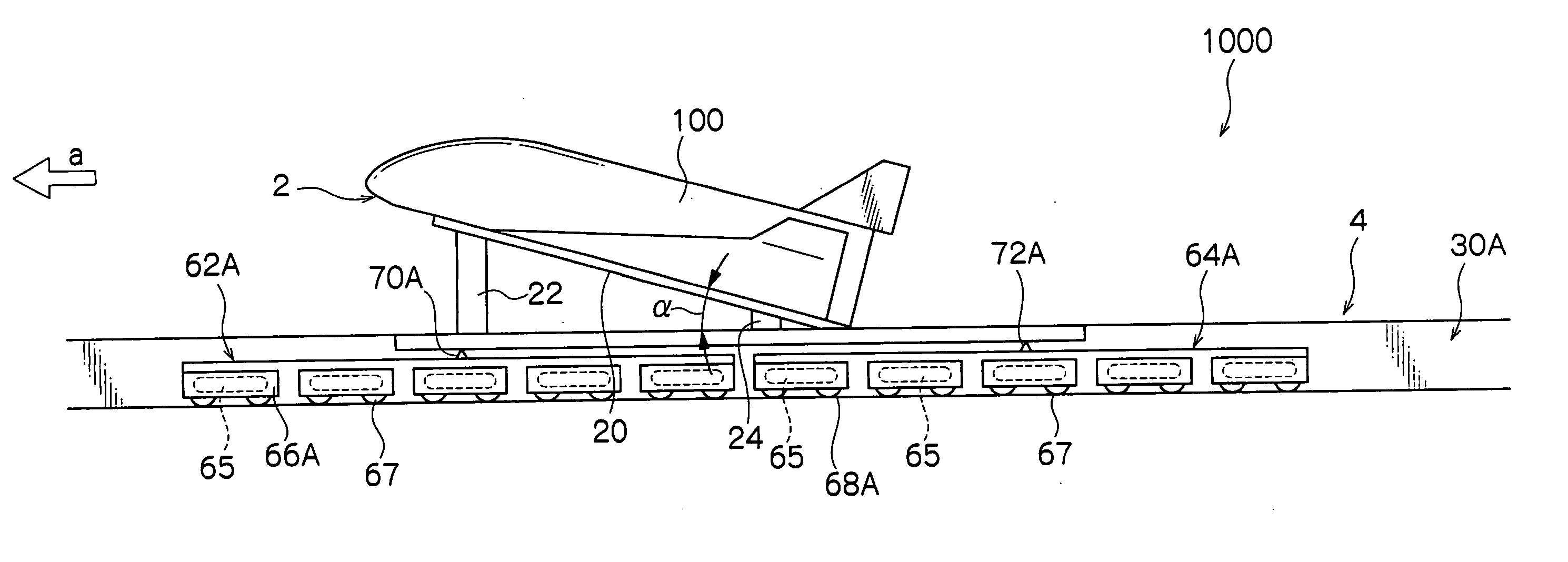
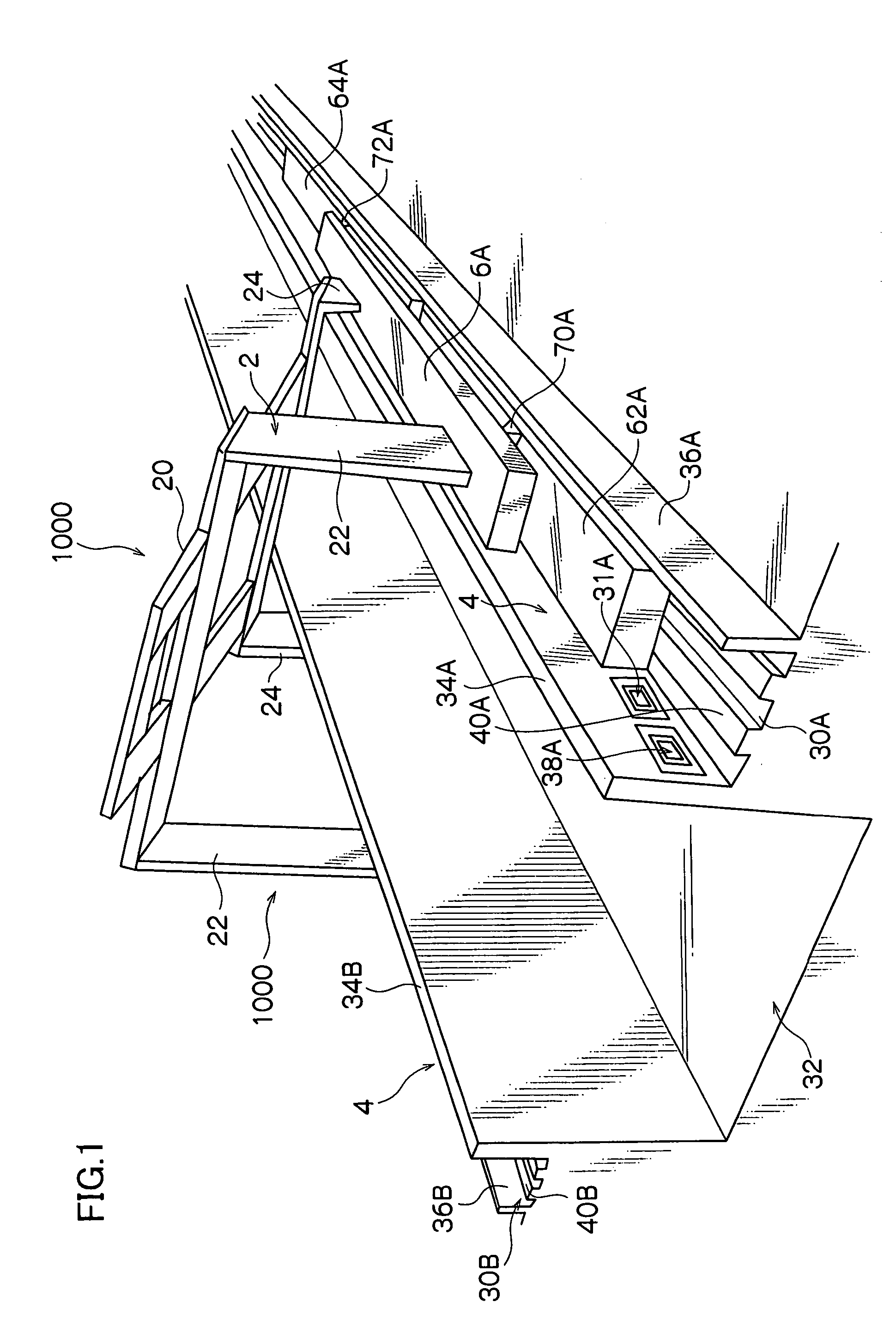
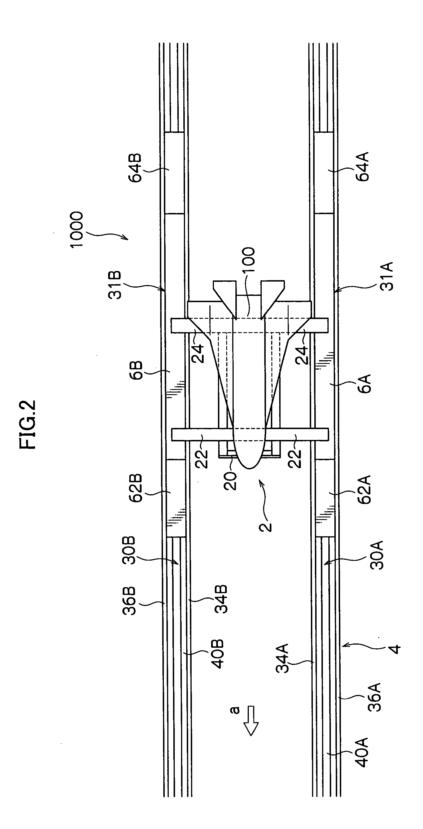
[0061] As shown in FIGS. 1 to 4, a horizontal launching apparatus 1000 relating to the first embodiment has a carrier device 2 carrying a spacecraft craft 100 when launching it horizontally, and a pair of tracks 4 on which the carrier device 2 travels.

[0062] The carrier device 2 has a spacecraft-supporting platform 20 and carriage portions 6A and 6B travelling along each of the tracks 4. The spacecraft-supporting platform 20 is fixed to the carriage portions 6A and 6B by frontal struts 22 and rear struts 24 so that a mounting surface of the spacecraft-supporting platform 20 on which the spacecraft 100 is mounted and a horizontal surface make an angle of attack α that is positive with a traveling direction ‘a’. The angle of attack α can be determined such that the spacecraft 100 is released with certainty from the spac...


PUM


Abstract

A flying vehicle-launching apparatus and method for launching a winged flying vehicle by accelerating the vehicle in a predetermined direction includes a flying vehicle-supporting platform, a guide device, and a driving device. The flying vehicle-supporting platform supports the winged flying vehicle so that it can lift off therefrom. The guide device supports the flying vehicle-supporting platform across two or more separated and parallel guide ways and guides the flying vehicle-supporting platform along the guide ways. In the flying vehicle-launching method, a propulsive engine of the winged flying vehicle is started after initiating acceleration with a flying vehicle-accelerating device. The winged flying vehicle is released from the flying vehicle-accelerating device in a predetermined angle of attack that is positive to a direction of acceleration after reaching a predetermined velocity.

Description

CROSS-REFERENCE TO RELATED APPLICATION [0001] This application claims priority under 35 U.S.C. 119 to Japanese Patent Application No. 2003-359180, the disclosure of which is incorporated by reference herein. BACKGROUND OF THE INVENTION [0002] 1. Field of the Invention [0003] The present invention relates to an apparatus and method for launching a winged flying vehicle, especially, an apparatus and method suitable for horizontally launching a flying vehicle such as a spacecraft. [0004] 2. Description of the Related Art [0005] Vertically launched rockets such as those used with the Space Shuttle are commonly known as flying vehicles used for space travel. However, vertically launched spacecraft are considered uneconomical in that fuel occupies a large portion of the spacecraft lift-off weight and furthermore, it is difficult to reuse the fuselage. [0006] Therefore, spacecraft that take off and land horizontally like a common aircraft have recently been attracting attention since such ...

Claims


Application Information

Patent Timeline
IPC IPC(8): B64F1/04B64G1/00B64G1/14B64G5/00
CPCB64F1/04B64G5/00B64G1/14B64G1/002
Inventor YAMAMOTO, MASATADA
Owner CENTRAL JAPAN RAILWAY COMPANY
Learn More