Assembly of motor vehicle body and a power train and chassis module

Inactive Publication Date: 2005-04-21
ASTON MARTIN LAGONDA LIMITED
View PDF10 Cites 18 Cited by
  • Summary
  • Abstract
  • Description
  • Claims
  • Application Information

AI Technical Summary

Benefits of technology

[0006] Accordingly, it is the advantage of the present invention to disclose a motor vehicle with passenger compartment, a subframe that supports the rear suspension and engine, a torque tube rigidly attached to the engine, and a power train and chassis module that simplify motor vehicle assembly.
[0007] It is further the advantage of the present invention to disclose a method for manufacturing a motor vehicle with passenger compartment that includes a subframe which supports the rear suspension and engine, a torque tube rigidly attached to the engine, and a power train and chassis module.
[0008] It is the advantage of the present invention to provide a subframe with front, main and intermediate longitudinal beams that vary in length according to the type of motor vehicle used.
[0009] It is moreover, the advantage of this invention to determine the dimensiosn of certain module components by the required length of longitudinal members.
[0010] According to a first aspect of the invention there is provided a motor vehicle having a power train and chassis module, said module including a front subframe for the suspension of front wheels of the vehicle and having a rear vertical mounting face, an engine mounted in the front subframe, a torque tube rigidly attached to the rear of the engine and extending long

Problems solved by technology

The problem with such an energy absorbing front-end structure is that the engine cannot be easily fitted to th

Method used


Image

  • Assembly of motor vehicle body and a power train and chassis module
  • Assembly of motor vehicle body and a power train and chassis module
  • Assembly of motor vehicle body and a power train and chassis module

Examples


Example

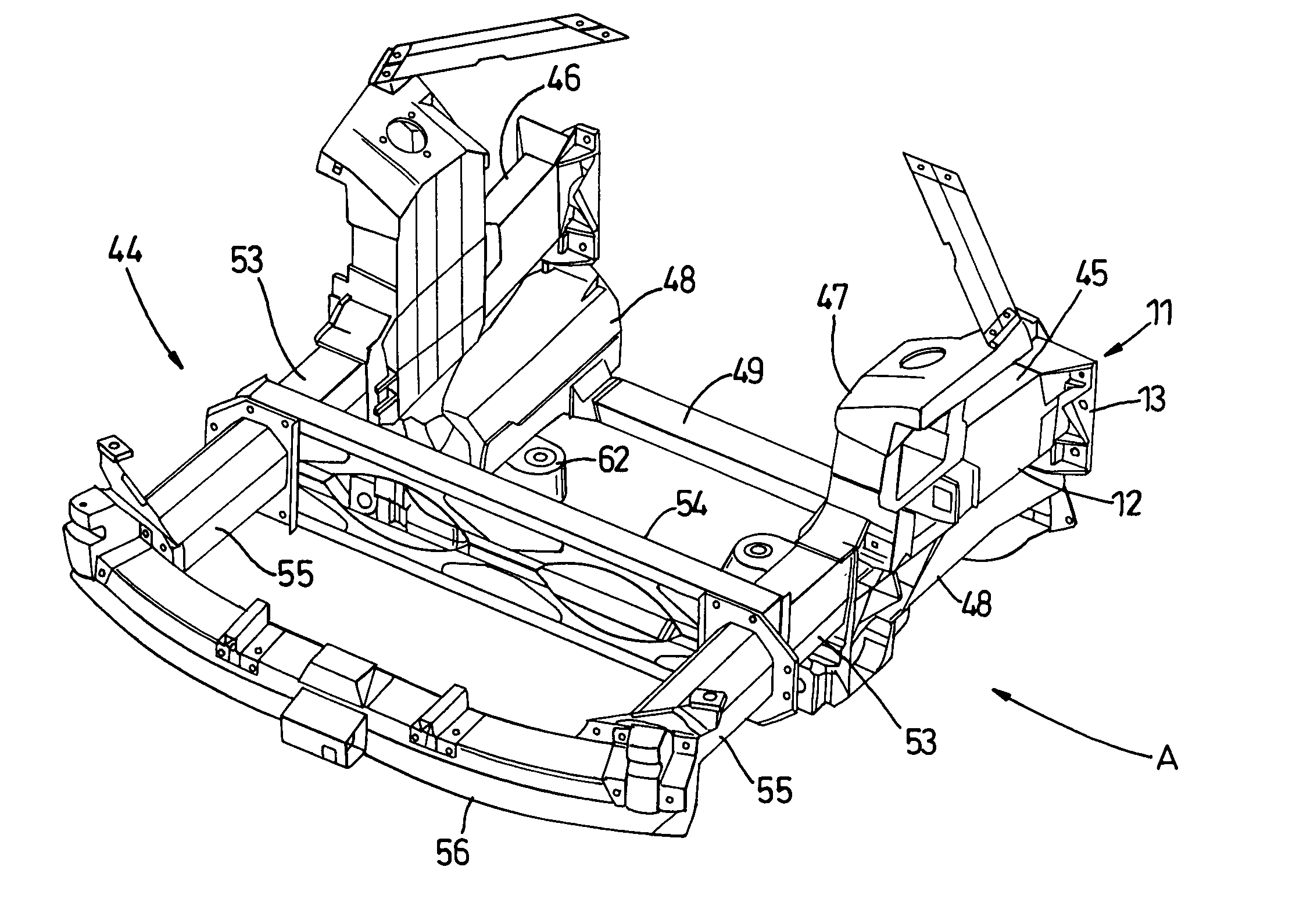
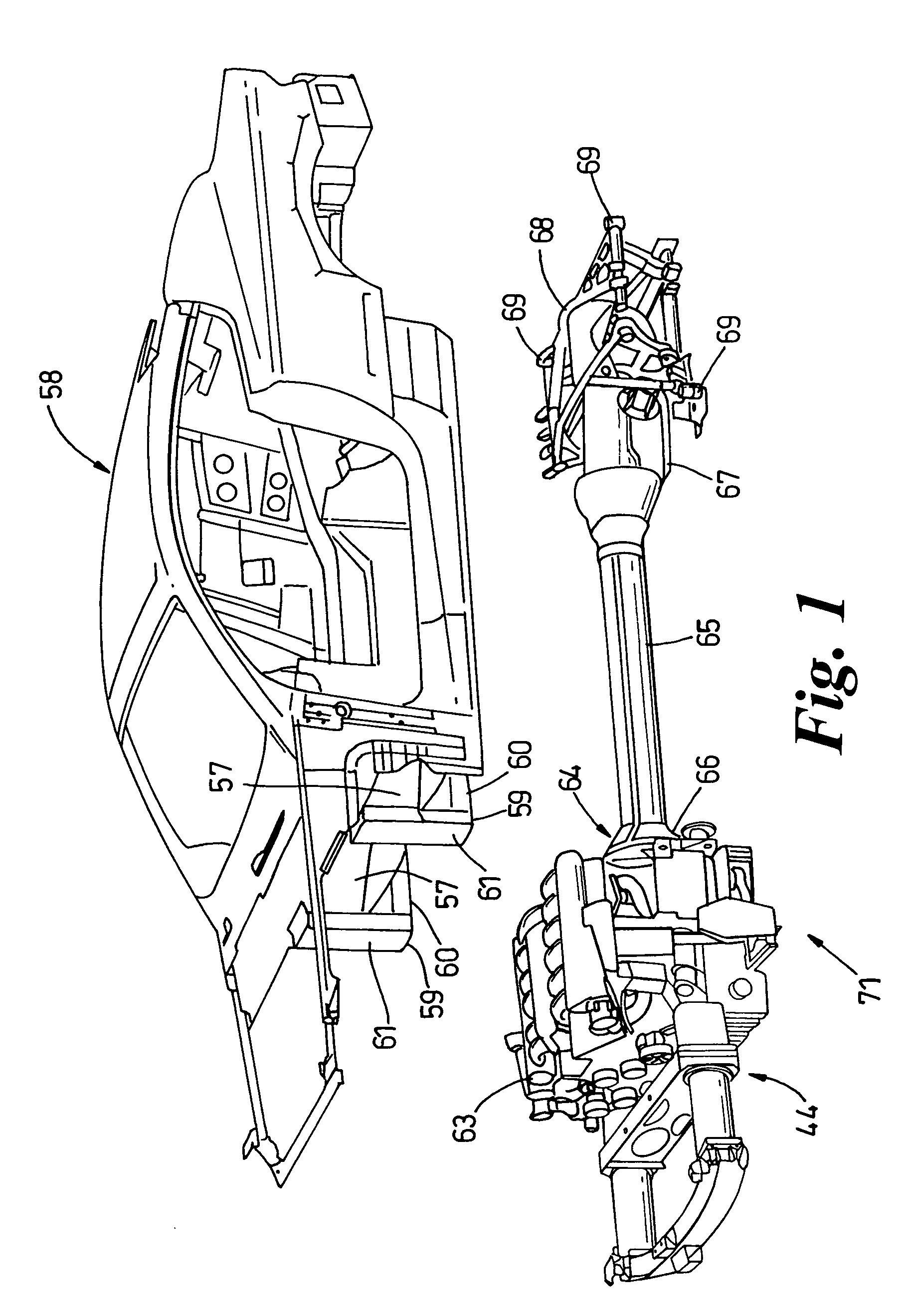
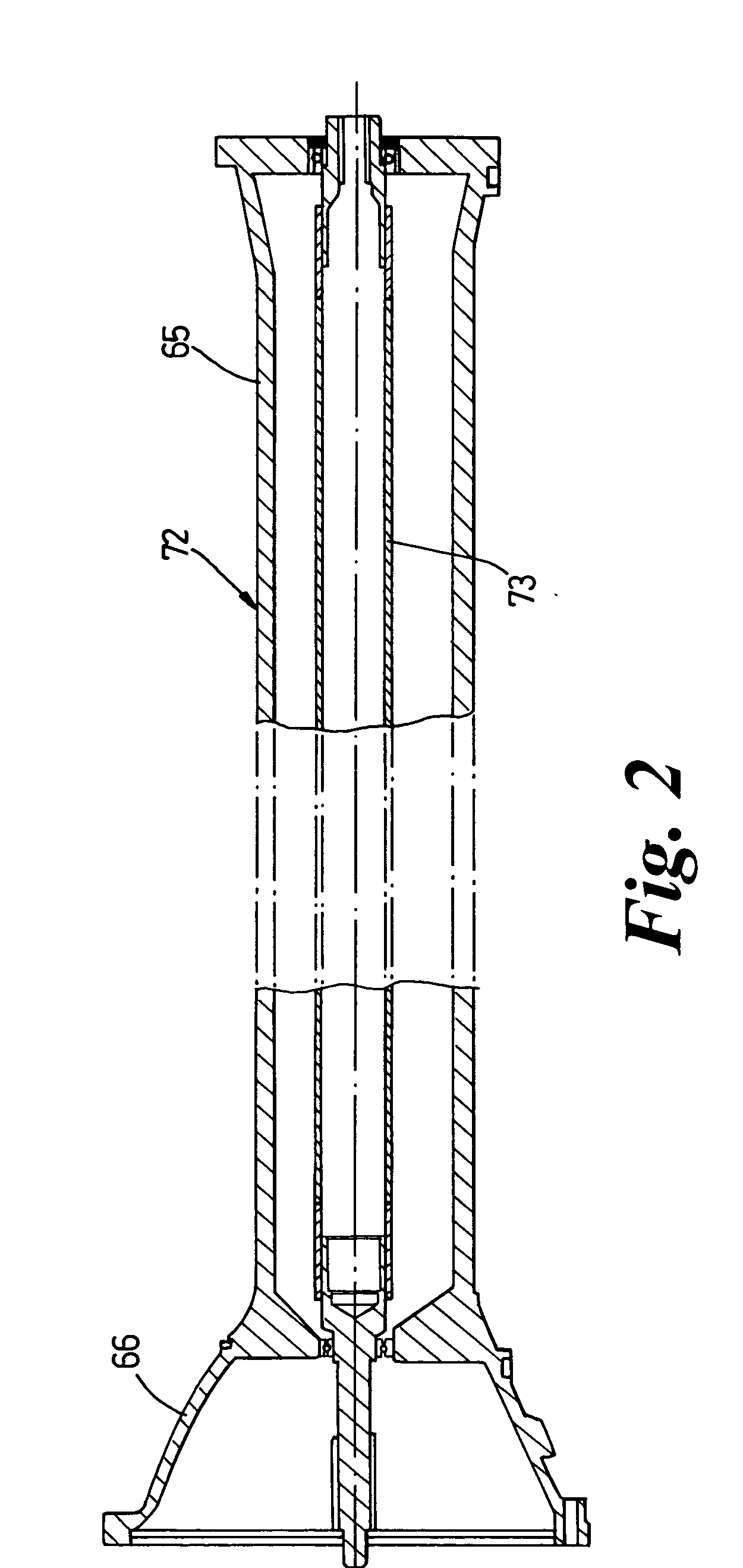
[0026] Referring now to the drawings, FIG. 1 shows a motor vehicle that has a vehicle body 58 with passenger compartment. As shown in FIG. 1, the body 58 is being assembled to a power train and chassis module 71 which comprises a powertrain assembly 64 and front and rear subframes 44, 68. The powertrain assembly 64 includes an engine 63, a longitudinally extending torque tube 65 attached to the rear of the engine by a bell housing 66 and a rear transmission and final drive assembly or transaxle 67 attached to a rearward end of the torque tube 65 for driving rear wheels of the vehicle. The torque tube 65 and the bell housing 66 are formed as a single casting and form part of a torque tube and drive shaft assembly 72 as seen more clearly in FIG. 2. The torque tube and the bell housing casting rigidly connects the block of the engine 63 and to the casing of the transaxle 67 while a drive shaft 73 carried in bearings within the torque tube 65 can transmit power from the engine 63 to the...


PUM


Abstract

A motor vehicle front subframe includes a pair of main longitudinal beams each formed from an extrusion with a flange casting at the rear end and a suspension tower at the other end. Two lower longitudinal beams extend parallel to the main longitudinal beams and are connected by a cross member. Each lower longitudinal beam has a vertical rear flange and a generally horizontal front flange where it is attached to a corresponding flange face at the lower end of the adjacent suspension tower. Two intermediate longitudinal beams are attached to the suspension towers and to a main cross-member and forward of this are two crush cans to which is attached a bumper armature. The front subframe is part of a power train and chassis module which includes an engine, a longitudinally extending torque tube attached to the rear of the engine by a bell housing, a rear transmission and final drive assembly attached to a rearward end of the torque tube and a rear subframe mounted on the rear transmission and final drive assembly. The vehicle has a body with a passenger compartment and vertical pillars just forward of the passenger compartment. The body is assembled to the power train and chassis module by lowering the body with the of the vertical pillars just clear of the rear faces of the flanges and until various fixing holes in the flanges and align with those in the pillars. The body is then moved forward to close the gap between the flanges and the pillars. Suitable bolts or set screws are then inserted to secure the front subframe to the body and the rear subframe is attached to the body.

Description

BACKGROUND OF THE INVENTION [0001] 1. Field of the Invention [0002] This invention relates to motor vehicles, methods of making motor vehicles and to certain components of such vehicles. [0003] 2. Description of Related Art [0004] Many passenger cars use a longitudinally arranged engine and transmission, where the transmission is located at the front of the vehicle with a rear mounted final drive that is connected to the transmission through a propshaft. It is common for passenger vehicles to use a torque tube to rigidly connect the engine and the transmission: the torque tube having a drive shaft running though it to transmit the drive from the engine to the transmission. Still the passenger compartment must be protected during frontal crashes. Most passenger cars use a front-end structure that is deformable in the longitudinal direction and absorbs energy during crash. The problem with such an energy absorbing front-end structure is that the engine cannot be easily fitted to the v...

Claims


Application Information

Patent Timeline
IPC IPC(8): B60K5/02B60K17/22B62D21/04B62D21/11B62D25/08B62D27/02B62D65/04F16L27/087
CPCB60K5/02B60K17/22B62D21/04B62D21/11F16L27/093B62D25/088B62D27/026B62D65/04B62D25/082B62D21/09B62D21/15B62D25/08B62D65/00
Inventor JOLLEY, PETER
Owner ASTON MARTIN LAGONDA LIMITED
Why Eureka
Try Eureka