Control apparatus of electricity accumulation mechanism

Active Publication Date: 2005-04-21
TOYOTA JIDOSHA KK
View PDF6 Cites 55 Cited by
  • Summary
  • Abstract
  • Description
  • Claims
  • Application Information

AI Technical Summary

Benefits of technology

[0010] Another object of the present invention is to suppress deterioration of the electricity accumulation mechanism.
[0025] According to the present invention, as the value related to actuation of the electricity accumulation mechanism, a value related to at least one of current values of charging power to the electricity accumulation mechanism and discharging power from the electricity accumulation mechanism, temperature of the electricity accumulation mechanism and a rate of change in an acceleration pedal position is detected. Here, the deterioration degree of the electricity accumulation mechanism depends on current values of charging power to the electricity accumulation mechanism and discharging power from the electricity accumulation mechanism, and temperature of the electricity accumulation mechanism. Additionally, when charging power to the electricity accumulation mechanism and discharging power from the electricity accumulation mechanism are controlled in accordance with a rate of change in an acceleration pedal position, the deterioration degree of the electricity accumulation mechanism depends on the rate of change in an acceleration pedal position. Therefore, by detecting a value on which a deterioration degree of the electricity accumulation mechanism depends, and determining the deterioration degree of the electricity accumulation mechanism based on the history of the detected value, the deterioration degree can be determined precisely.

Problems solved by technology

Such a capacitor or battery has a property that it deteriorates by loads and that the performance is impaired.
Thus, there has been a problem that the performance of the electricity accumulation mechanism cannot fully be utilized.

Method used


Image

  • Control apparatus of electricity accumulation mechanism
  • Control apparatus of electricity accumulation mechanism
  • Control apparatus of electricity accumulation mechanism

Examples


first embodiment

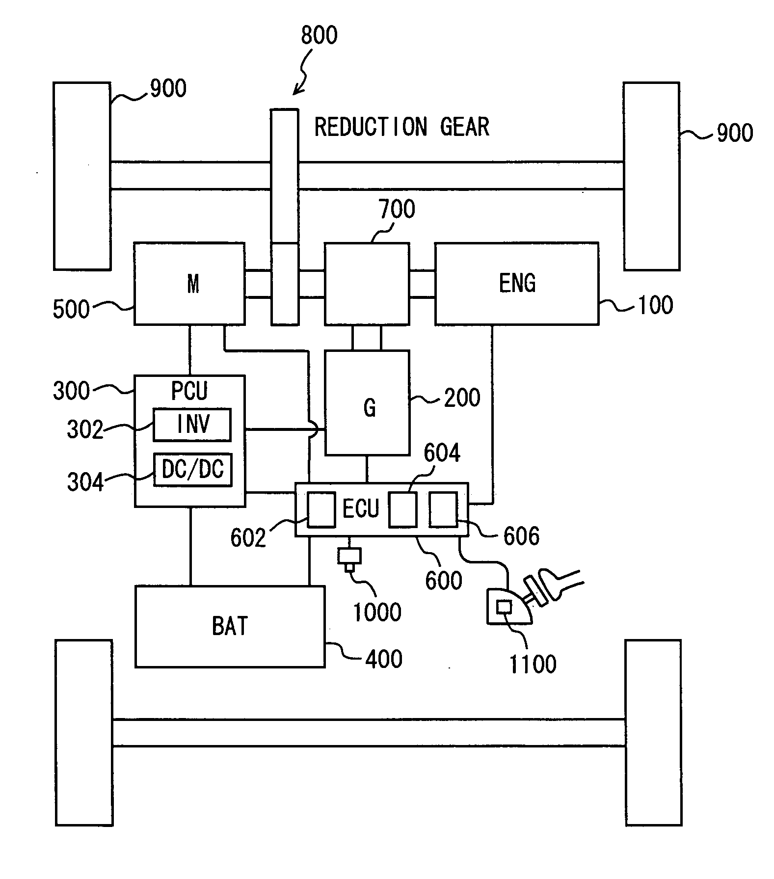
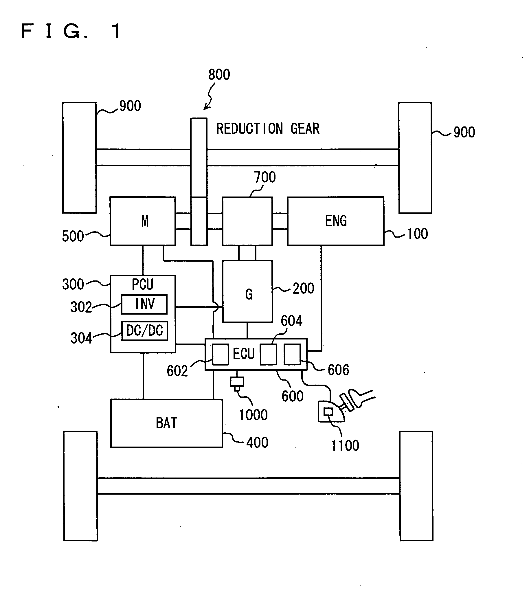
[0039] Referring to FIG. 1, a hybrid vehicle to which a control apparatus according to a first embodiment of the present invention is mounted includes an engine 100, a generator 200, a PCU (Power Control Unit) 300, a battery 400, a motor 500, and a hybrid ECU (Electronic Control Unit) 600 connected to all of these components. The control apparatus according to the embodiment of the present invention is realized by a program executed by hybrid ECU 600. While the present embodiment is described using a hybrid vehicle to which engine 100 is mounted, the present invention is not limited to a hybrid vehicle to which engine 100 is mounted and it is applicable to a hybrid vehicle to which a fuel cell is mounted in place of an engine (a fuel-cell vehicle), an electric vehicle to which only battery 400 is mounted or the like.

[0040] The motive power generated by engine 100 is split by a power split device. 700 into two routes. One of them is a route to drive wheels 900 through a reduction ge...

second embodiment

[0058] Referring to FIG. 7, a control apparatus according to a second embodiment of the present invention will be described. In the first embodiment described above, the maximum value of W(OUT) and the minimum value of W(IN) are not changed when the charging / discharging power regulation map is changed. On the other hand, in the present embodiment, the maximum value of W(OUT) and the minimum value of W(IN) are changed. Other hardware configuration and process flow are the same as in the first embodiment. Their respective functions are also the same. Accordingly, detailed description thereof will not be repeated here.

[0059] When the deterioration degree of battery 400 is determined to be greater than a predetermined value (YES at S200), as indicated by an alternate long and short dash line in FIG. 7, the charging / discharging regulation map is changes so that the regulation of charging / discharging power to / from battery 400 is tightened (S300). In the changed charging / discharging regul...

third embodiment

[0062] Referring to FIG. 8, a control apparatus according to a third embodiment of the present invention will be described. In the first embodiment described above, hybrid ECU 600 determines the deterioration degree of battery 400 using square-average value I2(AVE) of a charging / discharging current value and the load frequency thereof On the other hand, in the present embodiment, the deterioration degree of battery 400 is determined using battery temperature TB and the load frequency thereof Other hardware configuration and process flow are the same as in the first embodiment. Their respective functions are also the same. Accordingly, detailed description thereof will not be repeated here.

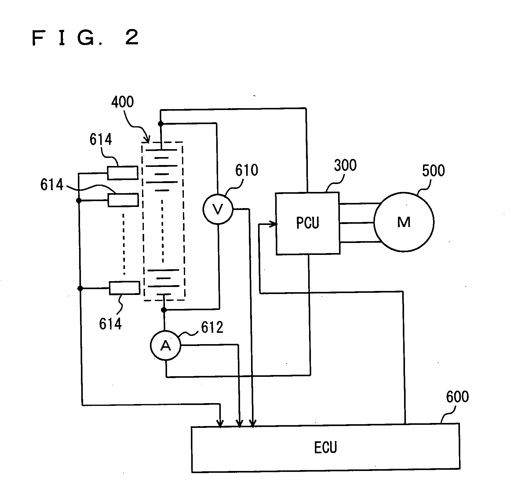
[0063] Hybrid ECU 600 calculates the load frequency for each battery temperature TB detected by battery temperature sensor 614. The method for calculating load frequency for each battery temperature TB is the same as the method for calculating the load frequency of square-average value I2(AVE) of ...


PUM


Abstract

A hybrid ECU executes a program that includes the steps of: determining whether a deterioration degree of a battery is greater than a predetermined degree; when the deterioration degree of the battery is greater than the predetermined value, tightening the regulation of charging / discharging power to / from the battery; determining whether the deterioration degree of the battery is smaller than the predetermined value and; when the deterioration degree of the battery is smaller than the predetermined value, relaxing the regulation of charging / discharging power to / from the battery.

Description

[0001] This nonprovisional application is based on Japanese Patent Application No. 2003-359126 filed with the Japan Patent Office on Oct. 20, 2003, the entire contents of which are hereby incorporated by reference. BACKGROUND OF THE INVENTION [0002] 1. Field of the Invention [0003] The present invention relates to a control apparatus regulating charging / discharging power of an electricity accumulation mechanism, and particularly, to a control apparatus of an electricity accumulation mechanism adjusting regulation in accordance with a deterioration degree of the electricity accumulation mechanism. [0004] 2. Description of the Background Art [0005] Recently, hybrid cars, fuel-cell vehicles and electric vehicles running by the drive power from a motor are attracting attention as a measure against environmental problems. To such a vehicle, a capacitor (condenser) or a battery (secondary cell) is mounted in order to accumulate power to be supplied to the motor. Such a capacitor or batter...

Claims


Application Information

Patent Timeline
IPC IPC(8): B60L11/18B60W10/26B60W20/00H01M10/44H02J7/00
CPCB60K6/445Y02T10/6239B60L3/0053B60L11/123B60L11/1851B60L11/187B60W10/26B60W20/00B60W2510/246B60W2540/10H02J7/0047H02J7/007Y02T10/6217Y02T10/7005Y02T10/705Y02T10/7077Y02T90/34B60L3/0046B60L50/61B60L58/10B60L58/24B60L58/12B60L58/18Y02T10/62Y02T10/70B60W2510/244H02J7/0048H02J7/005B60W20/13Y02T10/7072Y02T90/40
Inventor SUZUKI, YUSUKE
Owner TOYOTA JIDOSHA KK
Why Eureka
Try Eureka