Tandem rotation detector

Inactive Publication Date: 2005-04-21
MINEBEA CO LTD
View PDF6 Cites 0 Cited by
  • Summary
  • Abstract
  • Description
  • Claims
  • Application Information

AI Technical Summary

Benefits of technology

[0012] The present invention has been made in view of the above problems, and it is an object thereof to provide a tandem rotation detector capable of effectively preventing the occurrence of leakage flux between rotation angle detection mechanisms so that high-precision detection can be always realized.
[0018] The tandem rotation detector of the present invention includes the first rotation angle detection mechanism configured to generate a magnetic flux through the coil of the first outer core provided inside the cylindrical housing for detecting the rotation angle of the rotary shaft arranged in the central portion of the housing, and the second rotation angle detection mechanism which is placed side by side with the first rotation angle detection mechanism and configured to generate a magnetic flux through the coil of the second outer core provided inside the housing for detecting the rotation angle of the rotary shaft. In this structure, since current flows through the coil of the first outer core and the coil of the second outer core in different directions from each other, leakage flux between the rotation angle detection mechanisms can be effectively prevented, and hence high-precision detection can be always realized.
[0019] If one winding terminal of the coil of the first outer core and the other winding terminal of the coil of the second outer core, both of which are different in winding direction, are connected so that an AC voltage will be applied across the terminals, leakage flux between the rotation angle detection mechanisms can be prevented effectively in such a simple structure.
[0020] On the other hand, if the coils are wound on the first and second outer cores in the opposite directions, with the winding start terminals of the coils connected and the winding end terminals of the coils connected, respectively, so that an AC voltage will be applied across the connected terminals, leakage flux between the rotation angle detection mechanisms can also be prevented effectively in such a simple structure.

Problems solved by technology

The conventional tandem rotation detector, however, has the following problems.
Even in this case, the leakage flux still affects the performance of detecting the rotation angles.

Method used


Image

  • Tandem rotation detector
  • Tandem rotation detector
  • Tandem rotation detector

Examples


Embodiment Construction

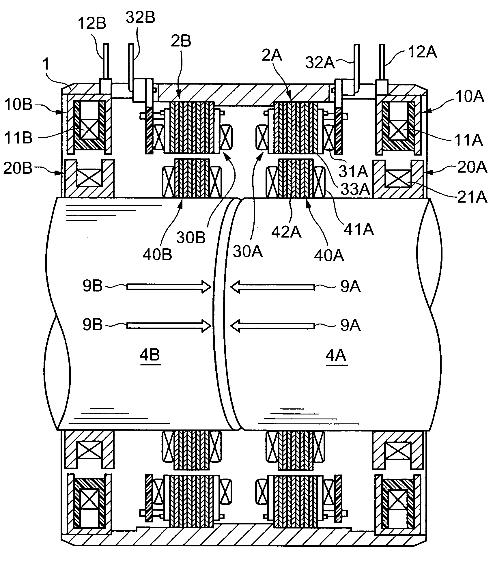
[0028] Tandem rotation detectors according to embodiments of the present invention will now be described with reference to the accompanying drawings.

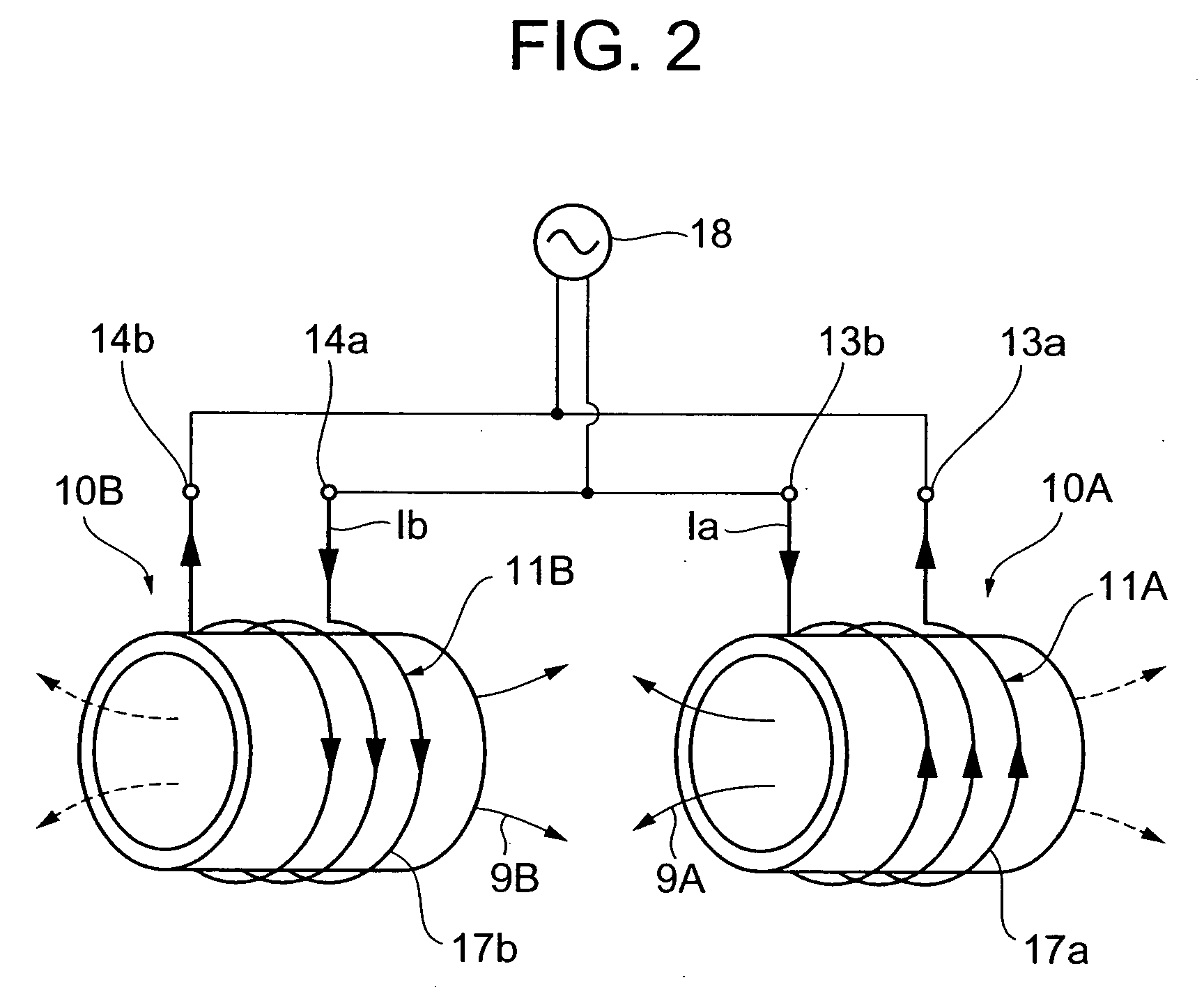
[0029]FIG. 2 is a connection diagram of a first outer core 10A and a second outer core 10B in a tandem rotation detector according to an embodiment of the present invention.

[0030] As shown in FIG. 2, wire 17a is wound around the first outer core 10A clockwise (as seen from the left in FIG. 2) from a winding terminal 13a to a winding 13b to form a coil 11A. Likewise, wire 17b is wound around the second outer core 10B clockwise from a winding terminal 14a to a winding terminal 14b to form a coil 11B. The winding terminal 13a and the winding terminal 14b are connected, and the winding terminal 13b and the winding terminal 14a are connected. In other words, wire connections are made between winding terminals different in winding direction from each other. An AC voltage from an AC oscillator 18 is applied across the winding terminals 13a a...


PUM


Abstract

A tandem rotation detector is provided for effectively preventing the occurrence of leakage flux between rotation angle detection mechanisms so that high-precision detection can be always realized. The tandem rotation detector of the present invention includes a first rotation angle detection mechanism 2A configured to generate a magnetic flux through a coil 11A of a first outer core 10A provided inside a cylindrical housing 1 for detecting the rotation angle of a rotary shaft 4A arranged in the central portion of the housing 1, and a second rotation angle detection mechanism 2B, placed side by side with the first rotation angle detection mechanism 2A, and configured to generate a magnetic flux through a coil 11B of a second outer core 10B provided inside the housing 1 to detect the rotation angle of a rotary shaft 4B, in which current flows through the coil 11A of the first outer core 10A and the coil 11B of the second outer core 10B in different directions from each other.

Description

BACKGROUND OF THE INVENTION [0001] 1. Field of the Invention [0002] The present invention relates to a tandem rotation detector capable of effectively preventing the occurrence of leakage flux between rotation angle detection mechanisms so that high-precision detection can be always realized. [0003] 2. Description of the Prior Art [0004]FIG. 1 shows a sectional side view of a conventional tandem rotation detector. [0005] As shown in FIG. 1, this type of tandem rotation detector (for example, Japanese Patent Application Laid-Open No. 2003-098019) is used to detect the rotation angles of rotary shafts. The rotation detector has a rotary shaft 104A and a rotary shaft 104B arranged in series in a central portion of a cylindrical housing 101. A first rotation angle detection mechanism 102A for detecting the rotation angle of the rotary shaft 104A, and a second rotation angle detection mechanism 102B for detecting the rotation angle of the rotary shaft 104B are arranged inside the housing...

Claims


Application Information

Patent Timeline
IPC IPC(8): G01B7/00G01B7/30G01D3/08G01D5/20G01L3/10
CPCG01D3/08G01L3/101G01D5/2006G01L3/105
Inventor MATSUURA, MUTSUMI
Owner MINEBEA CO LTD
Why Eureka
Try Eureka