Liquid crystal display backlight with modulation

a liquid crystal display and backlight technology, applied in the field of backlight displays, can solve the problems of limited ratio of luminance of dark and light areas or the dynamic range of an lcd, and the image displayed on this type of panel may be difficult to see,

Inactive Publication Date: 2005-04-21
SHARP KK
View PDF99 Cites 53 Cited by
  • Summary
  • Abstract
  • Description
  • Claims
  • Application Information

AI Technical Summary

Problems solved by technology

Since the panel is not completely transparent, a substantial part of the light is absorbed during its transits of the panel and images displayed on this type of panel may be difficult to see except under the best lighting conditions.
However, a layer of translucent liquid crystals occupies a cell gap separating the two polarizers.
On the other hand, the use of LCDs in certain “high end markets,” such as medical imaging and graphic arts, is frustrated, in part, by the limited ratio of the luminance of dark and light areas or dynamic range of an LCD.
The primary factor limiting the dynamic range of an LCD is the leakage of light through the LCD from the backlight even though the pixels are in an “off” (dark) state.
Light leakage is the result of the limited extinction ratio of the cross-polarized LCD elements and is exacerbated by the desirability of an intense backlight to enhance the brightness of the displayed image.
While bright images are desirable, the additional leakage resulting from usage of a more intense light source adversely affects the dynamic range of the display.
However, these image processing techniques do not solve the problems of light leakage and the limited dynamic range of the LCD and can create imaging problems when the intensity level of a dark scene fluctuates.
However, the appearance of a small light object in one of a sequence of generally darker frames will cause a noticeable fluctuation in the light level of the darker images.

Method used


Image

  • Liquid crystal display backlight with modulation
  • Liquid crystal display backlight with modulation
  • Liquid crystal display backlight with modulation

Examples


Embodiment Construction

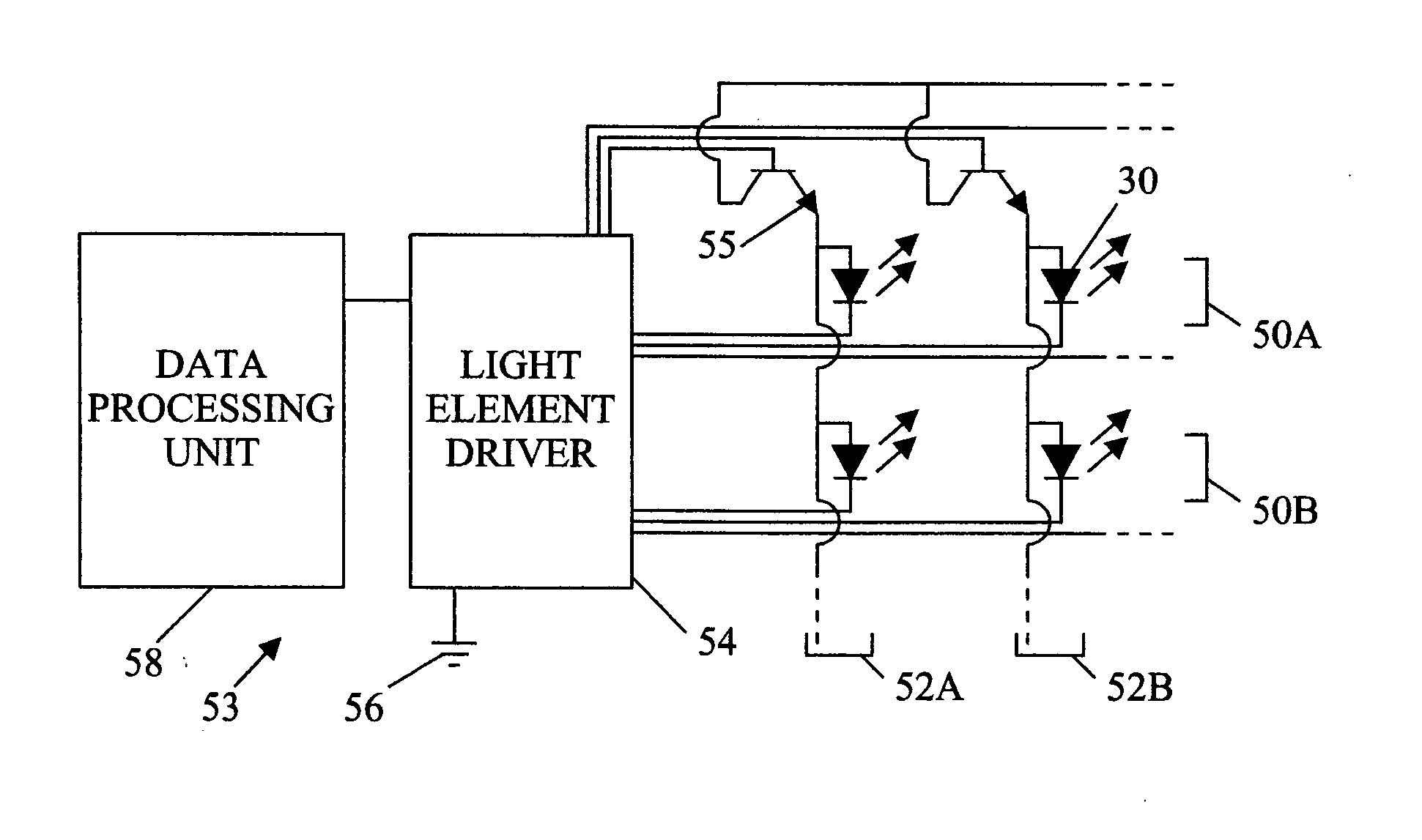
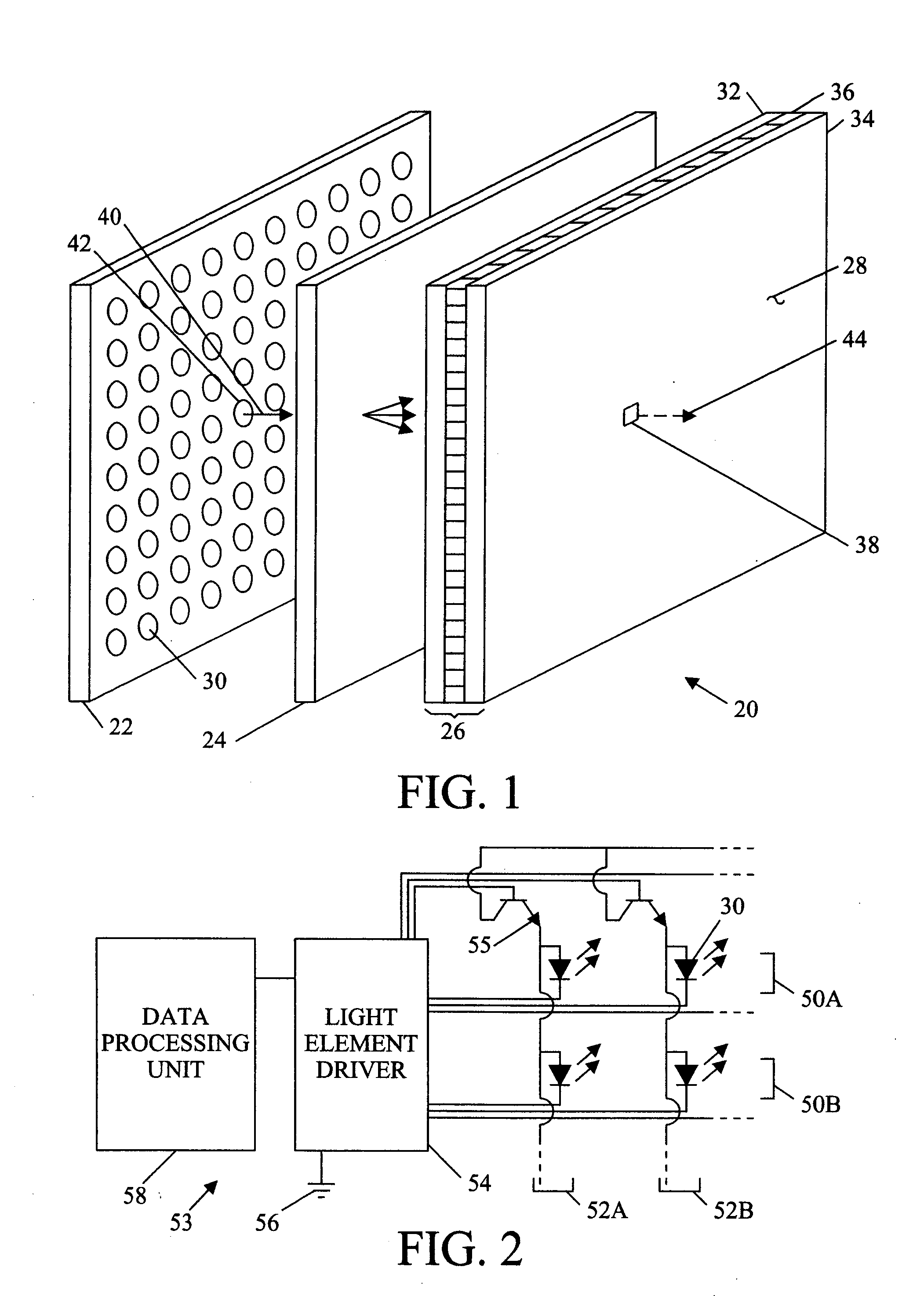
[0018] Referring to FIG. 1, a backlit display 20 comprises, generally, a backlight 22, a diffuser 24, and a light valve 26 (indicated by a bracket) that controls the transmittance of light from the backlight 22 to a user viewing an image displayed at the front of the panel 28. The light valve, typically comprising a liquid crystal apparatus, is arranged to electronically control the transmittance of light for a picture element or pixel. Since liquid crystals do not emit light, an external source of light is necessary to create a visible image. The source of light for small and inexpensive LCDs, such as those used in digital clocks or calculators, may be light that is reflected from the back surface of the panel after passing through the panel. Likewise, liquid crystal on silicon (LCOS) devices rely on light reflected from a backplane of the light valve to illuminate a display pixel. However, LCDs absorb a significant portion of the light passing through the assembly and an artificia...


PUM


Abstract

A display is backlit by a source having spatially modulated luminance to attenuate illumination of dark areas of images and increase the dynamic range of the display.

Description

CROSS-REFERENCE TO RELATED APPLICATIONS [0001] Not applicable. BACKGROUND OF THE INVENTION [0002] The present invention relates to backlit displays and, more particularly, to a backlit display with improved dynamic range. [0003] The local transmittance of a liquid crystal display (LCD) panel or a liquid crystal on silicon (LCOS) display can be varied to modulate the intensity of light passing from a backlit source through an area of the panel to produce a pixel that can be displayed at a variable intensity. Whether light from the source passes through the panel to an observer or is blocked is determined by the orientations of molecules of liquid crystals in a light valve. [0004] Since liquid crystals do not emit light, a visible display requires an external light source. Small and inexpensive LCD panels often rely on light that is reflected back toward the viewer after passing through the panel. Since the panel is not completely transparent, a substantial part of the light is absorb...

Claims


Application Information

Patent Timeline
Patent Type & Authority Applications(United States)
IPC IPC(8): G09G3/34
CPCG09G3/3426G09G2320/02G09G2320/0238G09G2360/16G09G2320/0285G09G2320/0646G09G2320/066G09G2320/0271
Inventor DALY, SCOTT J.
Owner SHARP KK
Why Eureka
Try Eureka