Retardation film and process for producing the same

Inactive Publication Date: 2005-04-21
HAYASHI TELEMPU CO LTD
View PDF9 Cites 9 Cited by
  • Summary
  • Abstract
  • Description
  • Claims
  • Application Information

AI Technical Summary

Benefits of technology

[0007] It is an object of the present invention to provide a retardation film capable of improving viewing angle characteristics of a TN liquid crystal display, i.e., capable of reducing a coloring phenomenon and gray scale inversion and to provide an industrial process for producing the retardation film.
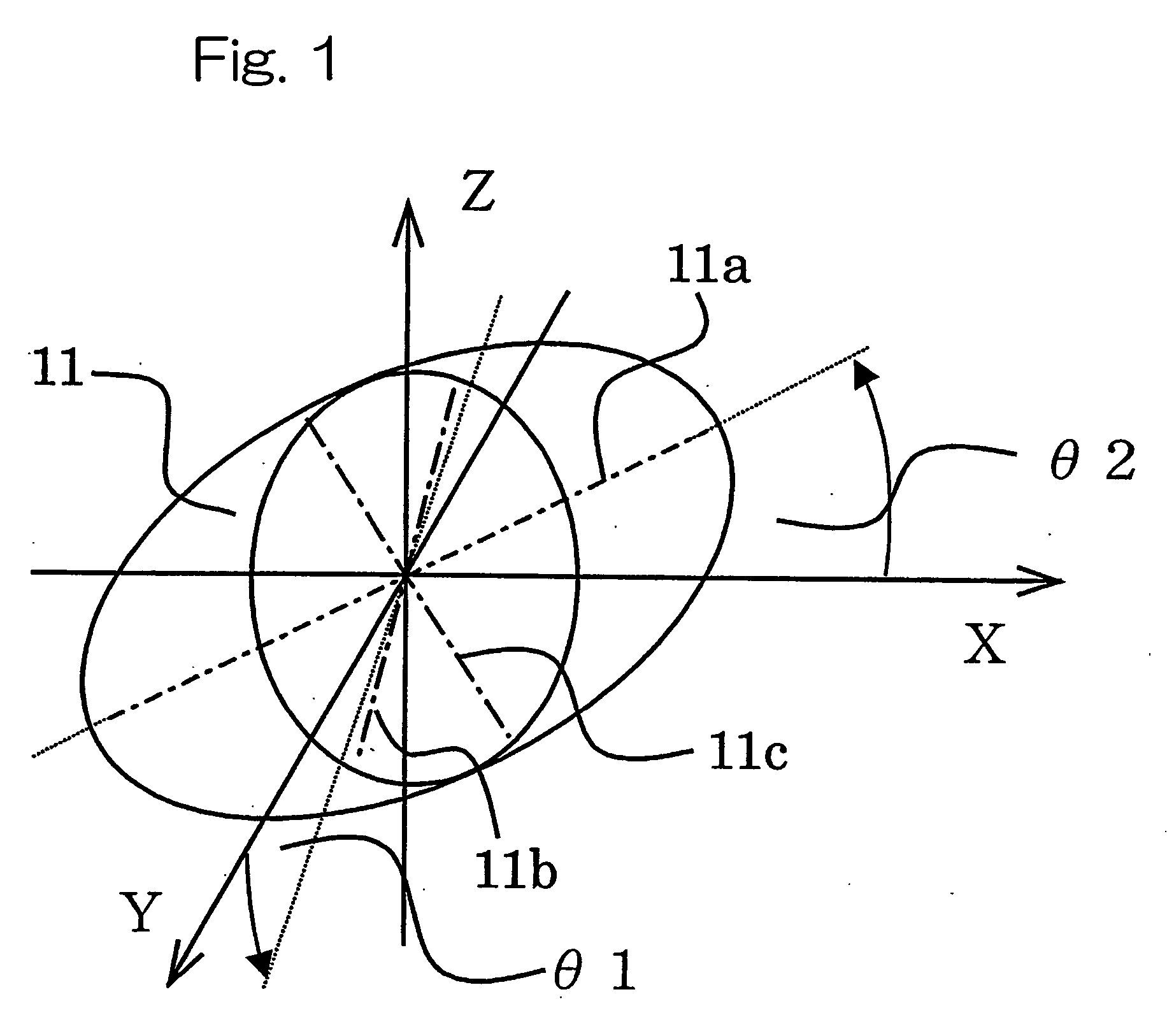
[0009] Since the first retardation film having the birefringence according to the present invention has primary refractive indexes nx′, ny′, and nz′ of the biaxial index ellipsoid in directions in which the biaxial index ellipsoid having primary refractive indexes nx, ny, and nz in X, Y, and Z axis directions is rotated at the angle θ01° about the X axis that is set as the axis of rotation and at the angle θ2° about the Y axis that is set as the axis of rotation, it is possible to provide the retardation film effective for reducing a coloring phenomenon and gray scale inversion and for enlarging a viewing angle of a liquid crystal display.
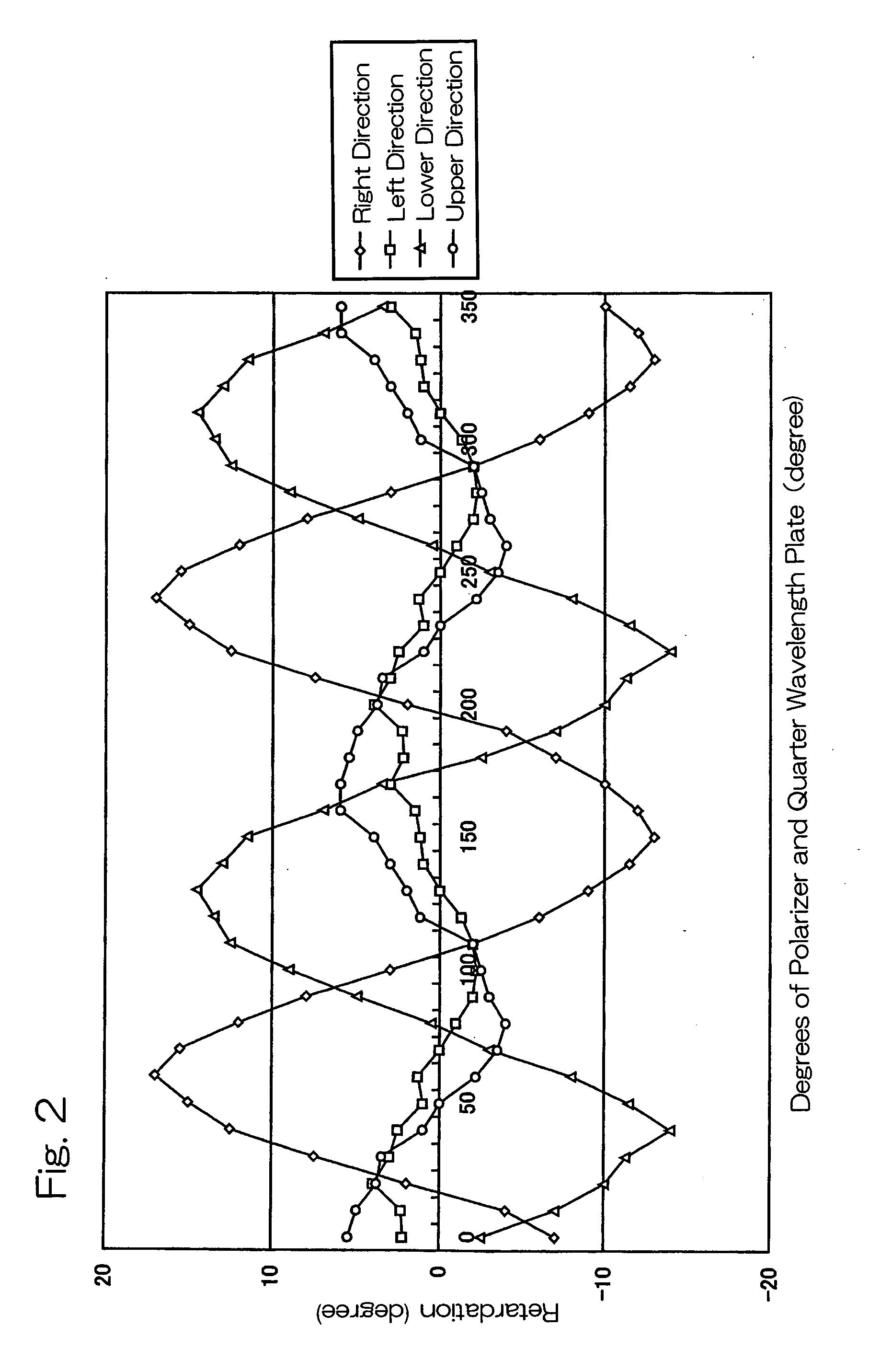
[0010] By attaching at least one retardation film between a liquid crystal cell and a polarizing plate in a TN liquid crystal display which consists of the liquid crystal cell having a TN liquid crystal put between two electrode substrates and two polarizing plates arranged on both sides of the liquid crystal cell, respectively, it is possible to reduce the coloring phenomenon and the gray scale inversion and improve the viewing angle characteristics of the TN liquid crystal display.
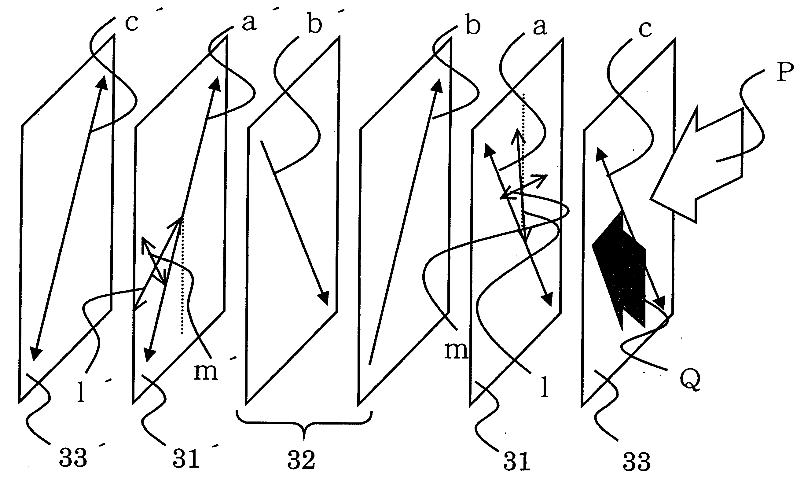
[0013] Since the second retardation film according to the present invention has the birefringence bearing a combination of the first index ellipsoid having primary refractive indexes nx in an X axis direction, ny in a Y axis direction and nz in a Z axis direction, where the primary refractive indexes nx, ny, and nz satisfy a relationship of nx>ny≧nz, and the second index ellipsoid having primary refractive indexes nx′, ny′, nz′, obtained by rotating the first index ellipsoid at an angle of θ3° about the Y axis as an axis of rotation and at an angle of θ4° about the Z axis as the axis of rotation, where the primary refractive indexes nx′, ny′, and nz′ satisfy a relationship of nx′>ny′≧nz′, if a plane formed by the X and Y axes represents the film surface and the Z axis conforms a direction of the film thickness, it is possible to provide the retardation film effective for reducing a coloring phenomenon and gray scale inversion and for enlarging a viewing angle of a liquid crystal display.
[0014] By attaching at least one retardation film between a liquid crystal cell and a polarizing plate in a TN liquid crystal display which consists of the liquid crystal cell having a TN liquid crystal put between two electrode substrates and two polarizing plates arranged on both sides of the liquid crystal cell, respectively, it is possible to reduce the coloring phenomenon and the gray scale inversion and improve the viewing angle characteristics of the TN liquid crystal display.

Problems solved by technology

Although such a retardation film can ensure an effect of greatly enlarging the angle of visibility, the sufficient optical compensation effect cannot be often attained, depending on a direction in which a user sees the liquid crystal display.
However, the discotic liquid crystal consists of a structure such as a triphenylene skeleton, and when the discotic liquid crystal is installed in the liquid crystal display, yellowish display appears at a large angle of view in a lateral direction due to the great wavelength dispersion, which disadvantageously degrades image quality of the liquid crystal display.
Therefore, the process disadvantageously involves complicated steps.
However, since this film uses the photoisomerization of azobenzene, it is considered to be impractical in terms of heat resistance, optical stability and the like.
However, in this publication, only the development of birefringence by irradiation with light is confirmed and no mention about practicability is made.
Therefore, this retardation film cannot ensure a sufficient optical compensation effect.

Method used


Image

  • Retardation film and process for producing the same
  • Retardation film and process for producing the same
  • Retardation film and process for producing the same

Examples


example 1

[0049] 4.2 wt % of the polymer (1) and 0.8 wt % of the low molecular compound (1) were dissolved in dichloroethane and the mixed solution was coated on a glass substrate (support) in a thickness of about 1 μm. The substrate was inclined at an angle of 60 degrees with respect to the horizontal plane and the substrate was arranged so that a coated surface becomes an irradiated surface. The substrate was irradiated with a linear polarized ultraviolet ray at an intensity of 100 mJ / cm2 so that the direction of the electric field oscillation of the ultraviolet ray is at 45° with respect to the inclined axis of the substrate. Next, the substrate was irradiated with the linear polarized ultraviolet ray at an intensity of 10 mJ / cm2 so that the direction of the electric field oscillation of the ultraviolet ray is at −45° with respect to the inclined axis of the substrate. Further, the substrate was turned upside down and similarly irradiated. Next, the resultant substrate was heated to 100° C...

example 2

[0068] 4.2 w t% of the polymer (1) and 0.8 wt % of the low molecular compound (1) were dissolved in dichloroethane and the mixed solution was coated on a glass substrate (support) in a thickness of about 1 μm. The substrate was inclined at an angle of 60 degrees with respect to the horizontal plane and the substrate was arranged so that a coated surface becomes an irradiated surface. The substrate was irradiated with an ultraviolet ray that consists of a perfectly polarized light component and a non-polarized light component and that has a degree of polarization of 69.4% (where the degree of polarization=perfectly polarized light component / (perfectly polarized light component+non-polarized light component)×100%)) at an intensity of 120 mJ / cm2 at room temperature from the direction perpendicular to the horizontal plane after the direction of the electric field oscillation of the perfectly polarized light component is rotated by 15° with respect to the inclined axis of the glass subst...


PUM


Abstract

A retardation film mainly used in a liquid crystal display and a process for producing the retardation film are provided. By using the retardation film having a birefringence, a coloring phenomenon and gray scale inversion can be reduced and viewing angle characteristics of a TN liquid crystal display can be improved.

Description

BACKGROUND OF THE INVENTION [0001] 1. Field of the Invention [0002] The present invention relates to a retardation film used to improve viewing angle characteristics of a liquid crystal display, and to a process for producing the retardation film. [0003] 2. Description of the Related Art [0004] Retardation films are films passing linear polarized light components oscillating in major axis directions orthogonal to each other and having birefringence providing a given retardation between these two components. Such retardation films are also utilized in the fields of liquid crystal displays. Particularly retardation films having liquid crystal materials having negative birefringences and slant-oriented or bent-oriented are utilized as optical compensation films that are effective for enlarging an angle of visibility of the liquid crystal display. Although such a retardation film can ensure an effect of greatly enlarging the angle of visibility, the sufficient optical compensation effec...

Claims


Application Information

Patent Timeline
IPC IPC(8): G02B5/30G02F1/1335G02F1/13363
CPCG02B5/3016G02F1/133634G02B5/3083
Inventor SAKAI, TAKEYAUETSUKI, MASAOKAWATSUKI, NOBUHIRO
Owner HAYASHI TELEMPU CO LTD
Why Eureka
Try Eureka