Roller bearing

a rolling bearing and roller bearing technology, applied in the direction of connecting rod bearings, knife-edge bearings, mechanical equipment, etc., can solve the problems of roundness security and expected to occur

Active Publication Date: 2005-04-21
NSK LTD
View PDF12 Cites 28 Cited by
  • Summary
  • Abstract
  • Description
  • Claims
  • Application Information

AI Technical Summary

Benefits of technology

[0009] The invention provides a roller bearing for rotatably supporting a rotating shaft of an internal combustion engine between a main body and a cap of the internal combustion engine, the roller bearing includes: a plurality of rollers; a retainer which is cirumferentially splittable and supports the plurality of rollers; and an outer race which is cirumferentially splittable and forms a raceway surface for the plurality of rollers; wherein the retainer is split into a plurality of retaining members; the outer race is split into a plurality of race plates; and at least one of the race plates is provided with one of a projection and a cavity to be engaged with one of the main body and the cap to restrict a relative movement between the one of the race plates and the one of the cylinder head and the cap.

Problems solved by technology

A similar problem occurs in a case where a crankshaft is supported between a cylinder block and a bearing cap.
In the case where the races and retainers are thus built in by being split, problems, such as the securing of roundness, are expected to occur which are essentially different from those of the case where cylindrical races are built in.

Method used


Image

  • Roller bearing
  • Roller bearing
  • Roller bearing

Examples


Embodiment Construction

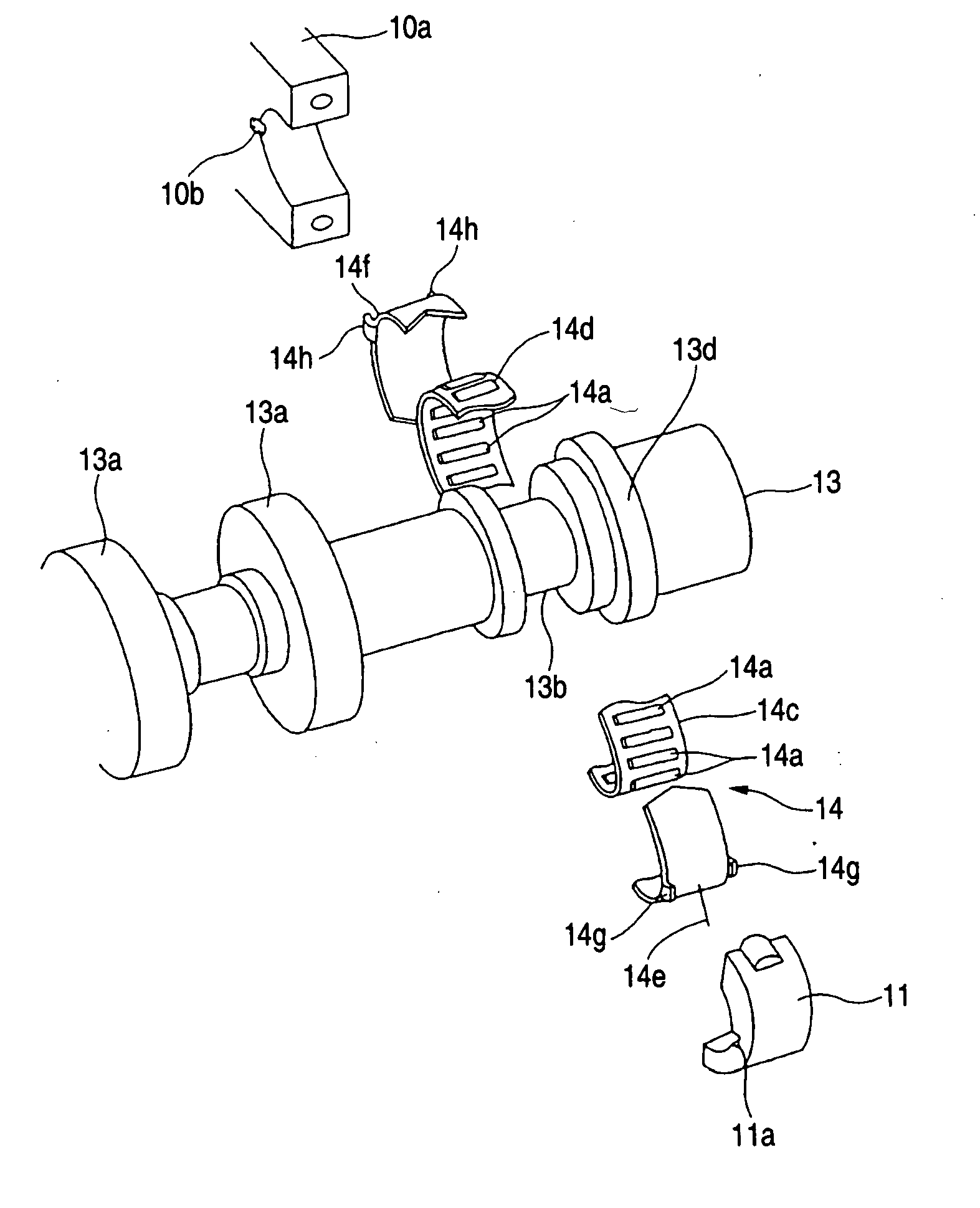
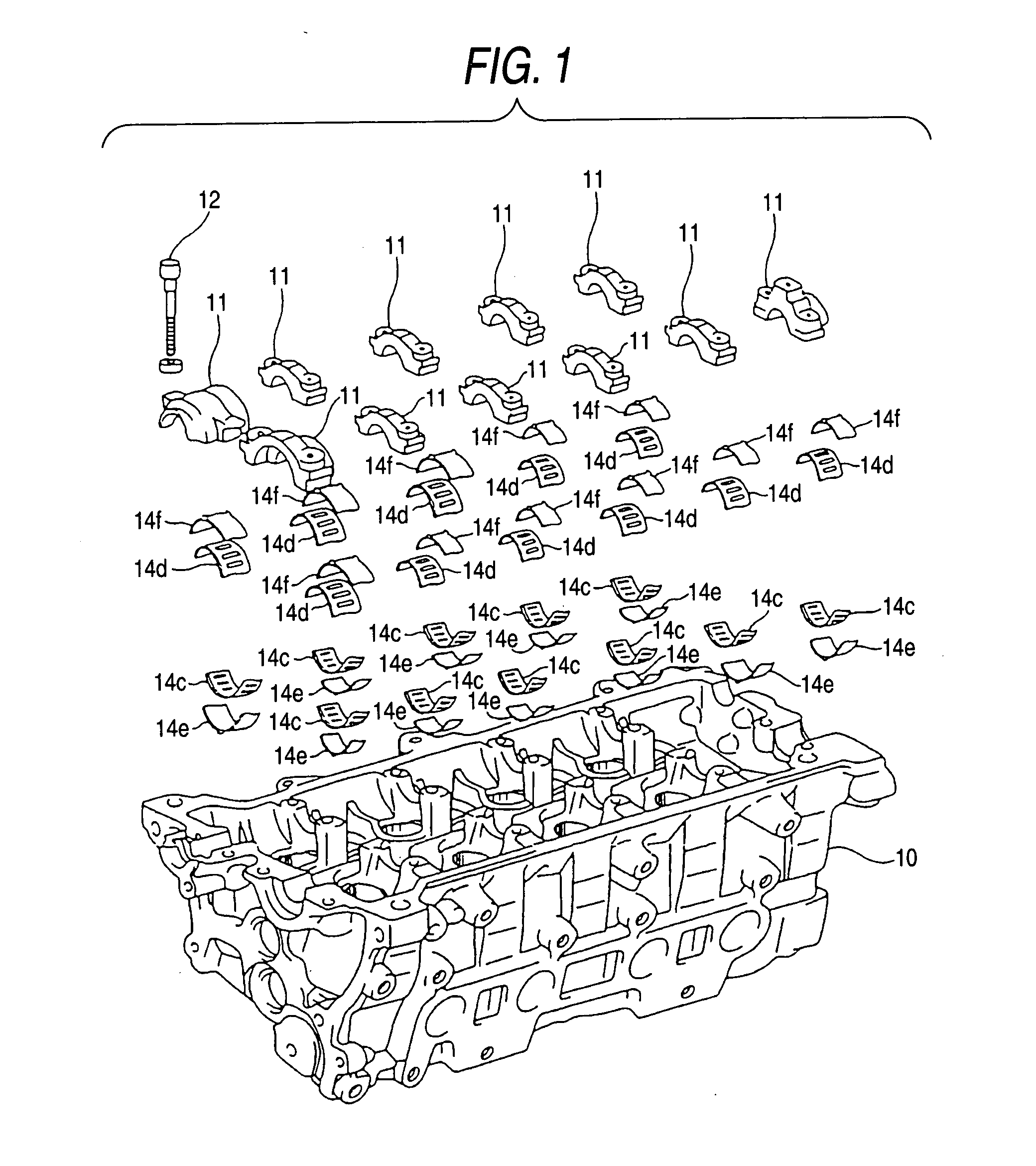
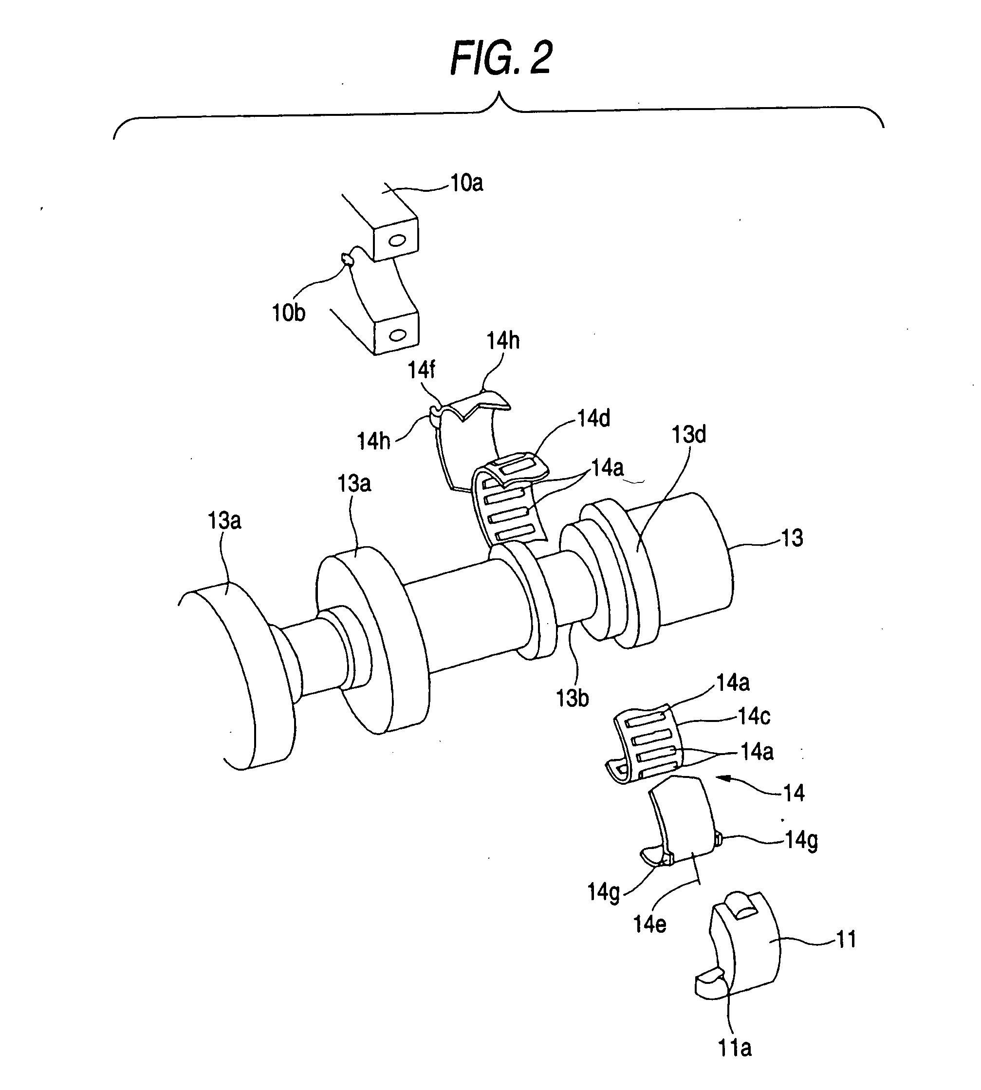
[0029] Hereafter, a detailed description will be given of an embodiment of the invention with reference to the drawings. FIG. 1 is an exploded view of a cylinder head of an internal combustion engine in accordance with this embodiment, but a camshaft is not shown. FIG. 2 is a partially enlarged view of the camshaft. In FIG. 1, the unillustrated camshaft is assembled to a cylinder head 10 as semiannular caps 11 are fitted on the camshaft and fastened to the cylinder head 10 by means of bolts 12 (only one bolt is shown).

[0030] In FIG. 2, a camshaft 13 has a pair of cam lobes 13a, a cylindrical journal portion 13b supported by a roller bearing 14, and a large-diameter end portion 13d. The outside diameter of the journal portion 13b is smaller than the largest dimension of each cam lobe 13a and the outside diameter of the large-diameter end portion 13d. The roller bearing 14 in this embodiment has a plurality of rollers 14a, circumferentially two-split substantially semicylindrical ret...


PUM

PropertyMeasurementUnit
diameteraaaaaaaaaa
temperatureaaaaaaaaaa
thicknessaaaaaaaaaa

Abstract

A roller bearing for rotatably supporting a rotating shaft of an internal combustion engine between a main body and a cap of the internal combustion engine. The roller bearing including: a plurality of rollers; a retainer which is cirumferentially splittable and supports the plurality of rollers; and an outer race which is cirumferentially splittable and forms a raceway surface for the plurality of rollers. The retainer is split into a plurality of retaining members. The outer race is split into a plurality of race plates. At least one of the race plates is provided with one of a projection and a cavity to be engaged with one of the main body and the cap to restrict a relative movement between the one of the race plates and the one of the cylinder head and the cap.

Description

BACKGROUND OF THE INVENTION [0001] 1. Field of the Invention [0002] The present invention relates to a roller bearing used in an internal combustion engine and an internal combustion engine using the same. [0003] 2. Background Art [0004] In an internal combustion engine, for example, in a case where a camshaft is rotatably supported in a cylinder head, sliding bearings are generally used. In recent years, however, the actual situation is such that attention has been focused on less fuel-consuming internal combustion engines from the viewpoints of such as effective utilization of resources and reduction of carbon dioxides. Accordingly, attempts have been made to further reduce the power loss in internal combustion engines by changing sliding bearings to rolling bearings whose drag resistance is generally smaller (refer to JP-A-8-128306). In particular, in the so-called DOHC-type internal combustion engines and V-type internal combustion engines, the number of camshafts becomes relati...

Claims


Application Information

Patent Timeline
Patent Type & Authority Applications(United States)
IPC IPC(8): F16C9/02F16C9/04F16C19/26F16C33/60F16C33/64
CPCF16C9/02F16C9/04F16C9/045F16C19/26Y10T29/49643F16C33/64F16C41/008Y10S384/906F16C33/60F16C2360/22
Inventor TAKEO, NORIYUKIKADOKAWA, SATOSHITAKAHASHI, AKIRA
Owner NSK LTD
Why Eureka
Try Eureka