Polarization retaining photonic crystal fiber

a polarization-maintaining and photonic crystal fiber technology, applied in the direction of optical fibers with polarisation, instruments, manufacturing tools, etc., can solve the problems of difficult splicing of two polarization-maintaining photonic crystal fibers, polarization planes cannot be identified, etc., to achieve easy splicing, easy identification, and easy fabricated

Inactive Publication Date: 2005-04-21
NIPPON TELEGRAPH & TELEPHONE CORP +1
View PDF2 Cites 15 Cited by
  • Summary
  • Abstract
  • Description
  • Claims
  • Application Information

AI Technical Summary

Benefits of technology

[0016] According to the invention of claim 3, the polarization plane can be readily identified with a commonly-employed optical microscope, or the like. Furthermore, the structure of the fiber is simple and therefore is readily fabricated. Thus, the production cost is further reduced as compared with the invention of claim 2. The hole diameter of the marking portion is preferably 2 μm or greater because, in such a case, excellent viewability is obtained. If t

Problems solved by technology

However, in the case of a polarization-maintaining photonic crystal fiber, the polarization planes cannot be identified by microscopically observing the fiber from the side because a region around the core, in which the polarizati

Method used


Image

  • Polarization retaining photonic crystal fiber
  • Polarization retaining photonic crystal fiber
  • Polarization retaining photonic crystal fiber

Examples


embodiment 1

[0028] (Embodiment 1)

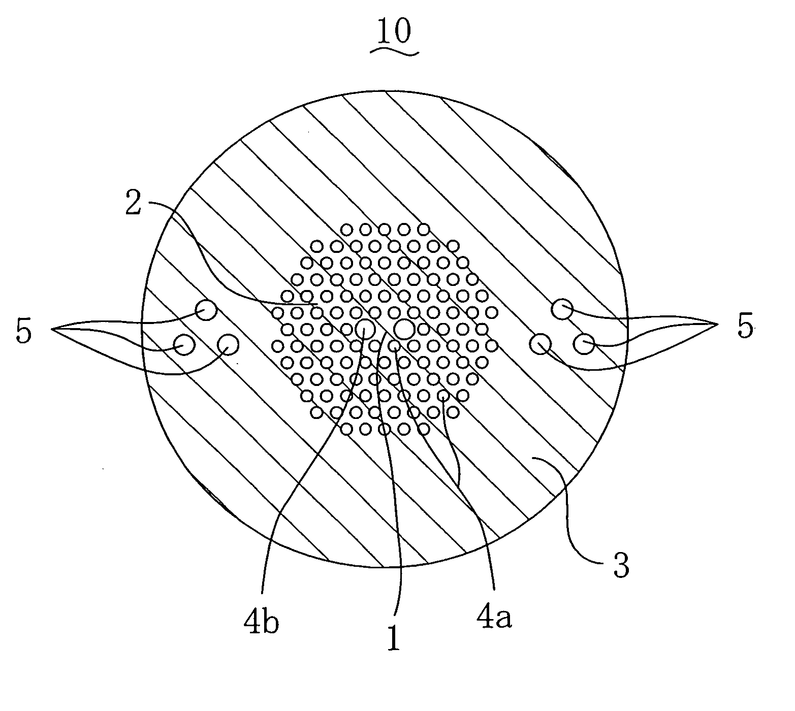
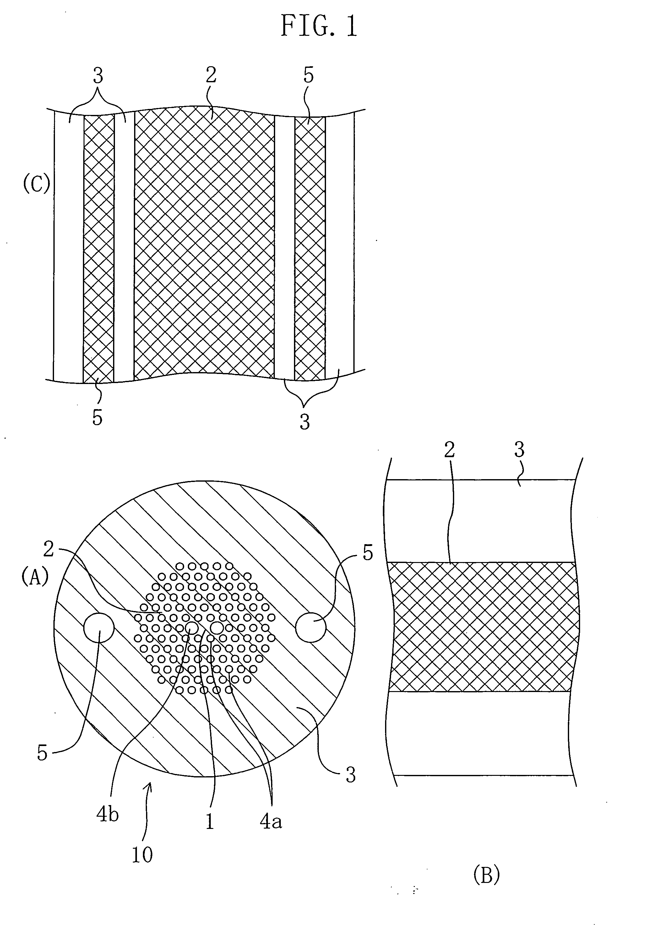
[0029]FIG. 1(A) is a cross-sectional view of a polarization-maintaining photonic crystal fiber 10 of embodiment 1. The polarization-maintaining photonic crystal fiber 10 includes a core 1 made of silica glass, a clad layer 2 surrounding the core 1, and an overclad layer 3 made of silica glass around the clad layer 2. The clad layer 2 includes a large number of thin holes 4a and 4b extending along the fiber axis. The thin holes 4a and 4b are arranged in a crystalline formation in which the minimum unit is a right triangular lattice. The overclad layer 3 has a pair of marking portions 5 at symmetric positions with respect to the core 1.

[0030] In the polarization-maintaining photonic crystal fiber 10, there are six thin holes 4a and 4b adjacent to the core 1. Among these holes, a pair of holes 4b at opposite sides of the core 1 have a diameter greater than that of the other four thin holes 4a. With such an arrangement of the thin holes 4a and 4b, the optical fiber...

embodiment 2

[0042] (Embodiment 2)

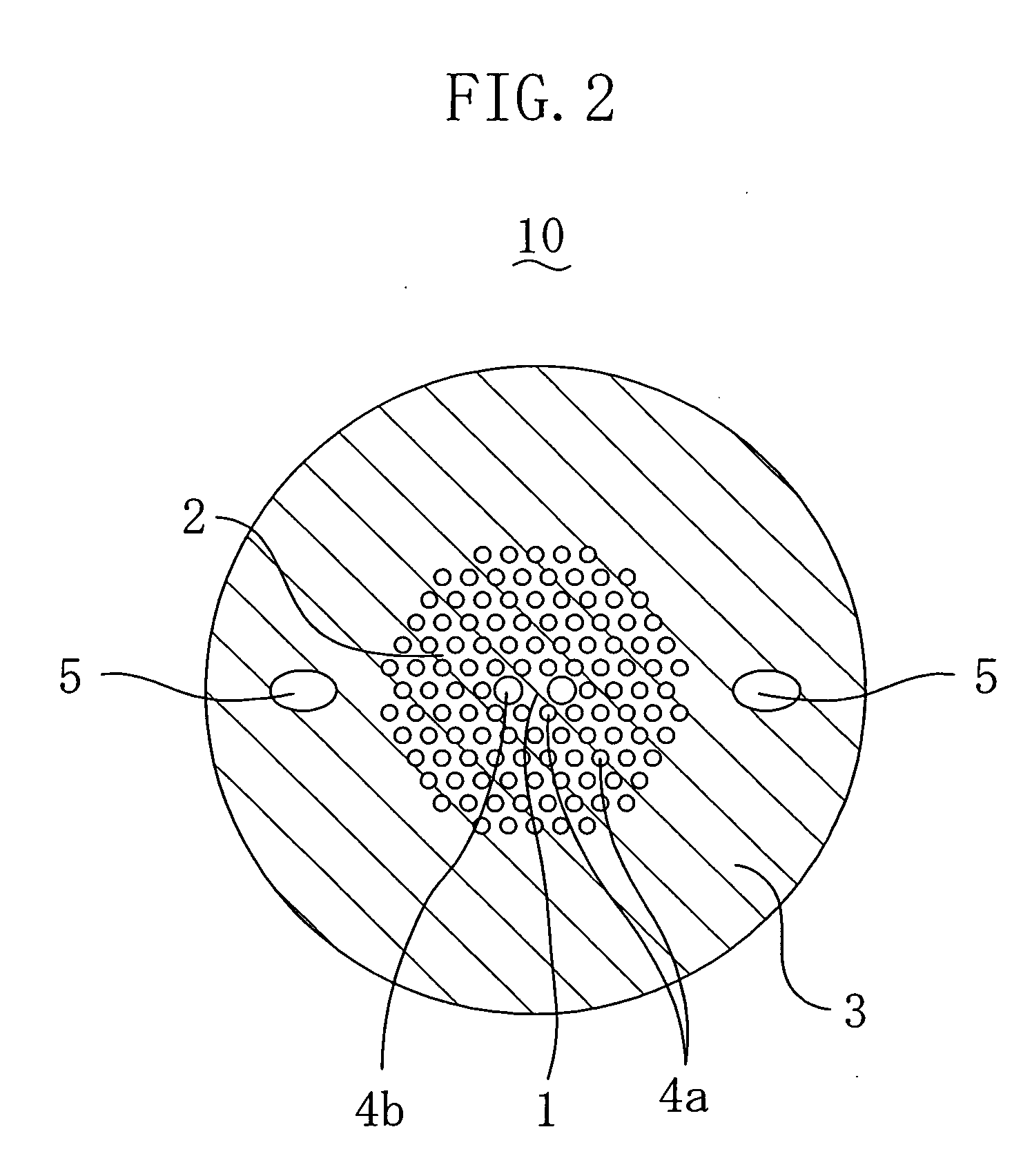
[0043]FIG. 2 is a cross-sectional view of a polarization-maintaining photonic crystal fiber 10 of embodiment 2. Embodiment 2 is different from embodiment 1 in that each of the marking portions 5 has an oval cross section. The direction of the major axis of the oval is generally equal to the direction in which a line between the centers of the two marking portions 5 extends. Herein, the major axis diameter of the oval of embodiment 2 is generally equal to the diameter of the circle of the marking portions 5 of embodiment 1. Thus, the viewability from the side of the fiber 10 is the same, but the inner surface area of the marking portion 5 per unit length of the fiber 10 is smaller in embodiment 2 than in embodiment 1. Thus, the number of rupture starting points which occur when the fiber is bent is smaller in embodiment 2 than in embodiment 1. That is, the fiber of embodiment 2 has a stronger mechanical strength than that of embodiment 1. The other functions and ...

embodiment 3

[0044] (Embodiment 3)

[0045]FIG. 3 is a cross-sectional view of a polarization-maintaining photonic crystal fiber 10 of embodiment 3. Embodiment 3 is different from embodiment 1 in that the marking portions 5 are holes having a smaller diameter than that of embodiment 1. The viewability from the side of the fiber 10 of embodiment 3 is inferior to that of embodiment 1. However, the inner surface area of the marking portion 5 per unit length of the fiber 10 is smaller in embodiment 3 than in embodiment 1. Thus, the fiber of embodiment 3 has a stronger mechanical strength than that of embodiment 1. The other functions and effects are equivalent to those of embodiment 1. The production method is also equivalent to that of embodiment 1.


PUM

PropertyMeasurementUnit
Diameteraaaaaaaaaa
Refractive indexaaaaaaaaaa

Abstract

A polarization-maintaining photonic crystal fiber 10 includes six thin holes 4a and 4b adjacent to a core 1. Among these holes 4a and 4b, a pair of holes 4b at opposite sides of the core 1 have a diameter greater than that of the other four thin holes 4a, and therefore, the polarization-maintaining photonic crystal fiber 10 has polarization-maintaining ability. An overclad layer 3 exists around the clad layer 2 which includes a large number of thin holes 4a and 4b around the core 1. The overclad layer 3 includes a pair of marking portions 5 at opposite sides of the core 1. The marking portions 5 are holes which can be seen at positions different from the clad layer 2 when the fiber 10 is viewed from a position right above the fiber 10 in the drawing. In this way, the direction of the polarization plane of the polarization-maintaining photonic crystal fiber 10 is identified.

Description

TECHNICAL FIELD [0001] The present invention relates to a polarization-maintaining photonic crystal fiber. BACKGROUND ART [0002] In recent years, photonic crystal fibers have been receiving attention as a fiber which achieves such a large chromatic dispersion that cannot be obtained in a commonly-employed optical fiber consisting of a core and a clad. The photonic crystal fibers consist of a core, a clad layer surrounding the core, which includes a large number of thin holes extending along the optical fiber axis and arranged in a crystalline formation, and an overclad layer surrounding the clad layer for supporting the clad layer. [0003] On the other hand, polarization-maintaining fibers, which have high polarization stability, are used for an optical fiber sensor which utilizes polarization and coherence, a coherent optical fiber communication system, etc. The above photonic crystal fiber has been studied for use as a polarization-maintaining photonic crystal fiber in view of its ...

Claims


Application Information

Patent Timeline
IPC IPC(8): C03B37/012G02B6/02G02B6/00G02B6/024G02B6/032
CPCC03B37/01217C03B37/0122C03B2203/14C03B2203/30G02B6/024G02B6/02333G02B6/02347G02B6/02357C03B2203/42
Inventor TANAKA, MASATOSHIYAMADORI, SHINYAFUJITA, MORIYUKIKAWANISHI, SATOKISUZUKI, KAZUNORIKUBOTA, HIROKAZU
Owner NIPPON TELEGRAPH & TELEPHONE CORP
Why Eureka
Try Eureka