
Portable drag box with automated shearing device

a drag box and automatic shearing technology, applied in the field of dragging boxes, can solve the problems of affecting the ride of finished pavement, affecting the smoothness of the applied material, and affecting the smoothness of the paved surface,

Inactive Publication Date: 2005-04-21
ARR MAZ PRODS
View PDF29 Cites 10 Cited by
  • Summary
  • Abstract
  • Description
  • Claims
  • Application Information

AI Technical Summary

Benefits of technology

[0010] According to the present invention, a portable drag box having a pugmill for use in laying asphalt mixtures on a surface is provided. This drag box is pulled behind a prime mover without being rigidly secured to the prime mover. The drag box further includes a strike blade for shearing the asphalt mixture to a desired thickness, cylinders for raising and lowering the strike blade in response to elevational changes in the surface being paved, and at least one signal generator associat...

Problems solved by technology

While screeds are commonly used to smooth hot mix paving material as it is applied, cold mix paving material is typically too viscous for conventional screeds to properly smooth the applied material.
Even in doing either or both, the ride of the finished pavement is compromised.
Thus, vertical movement of the prime mover is transferred to the screed, which can cause unwanted elevational changes to be created in the paved surface.
However, the lag time between the detection of a non-planar condition and the actual adjustment of the screed is too great with manual adjustment.
Again, the lag time between the detection of a non-planar surface and the actual adjustment of the blade tends to create more severe raised sections and indentations in the surface.
In addition, manual adjustment of the strike blade is costly as an additional operator must stand on the grate of the drag box to adjust the strike blade while other operators operate the prime mover that pulls the drag box.

Method used


Image

  • Portable drag box with automated shearing device
  • Portable drag box with automated shearing device
  • Portable drag box with automated shearing device

Examples


Embodiment Construction

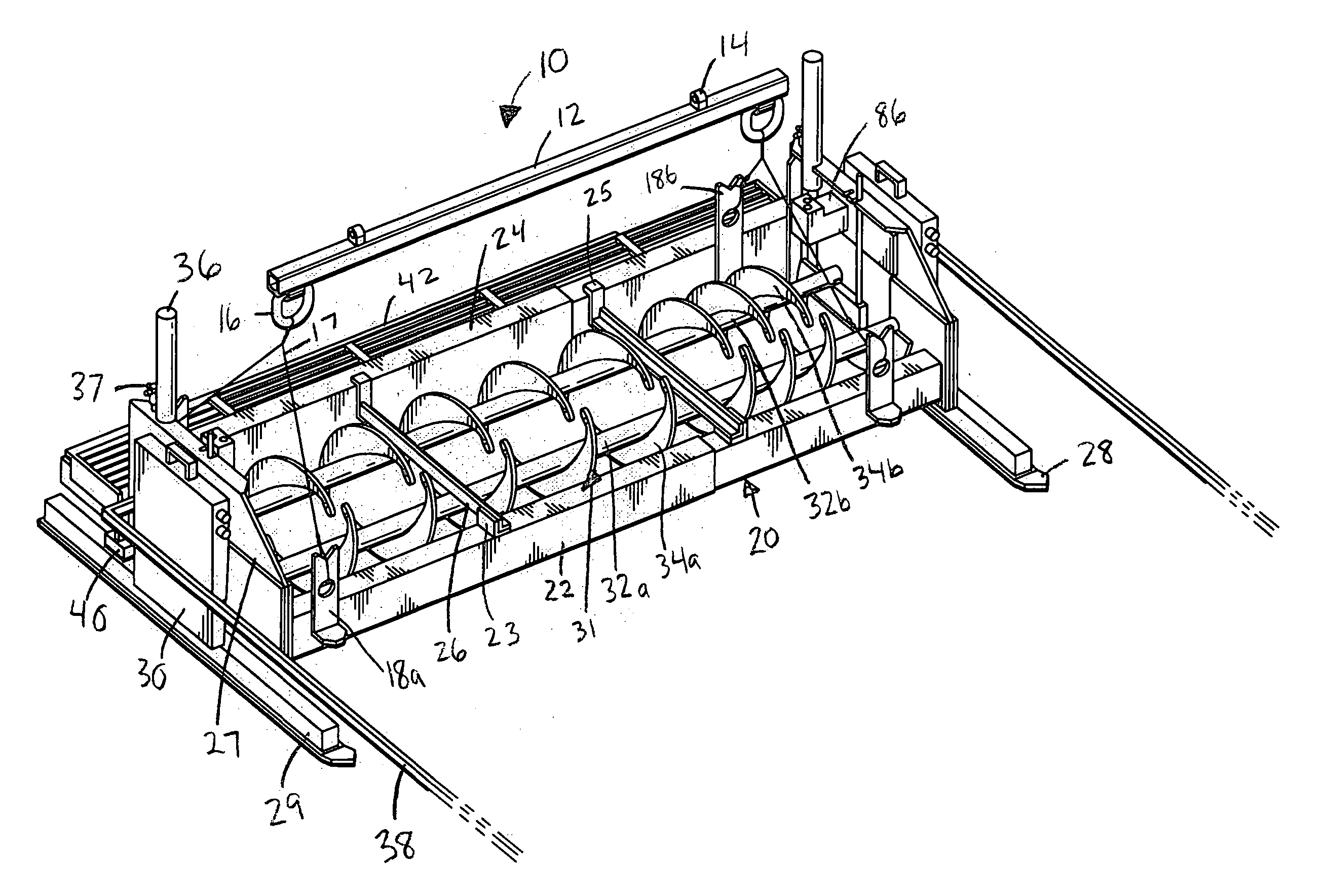
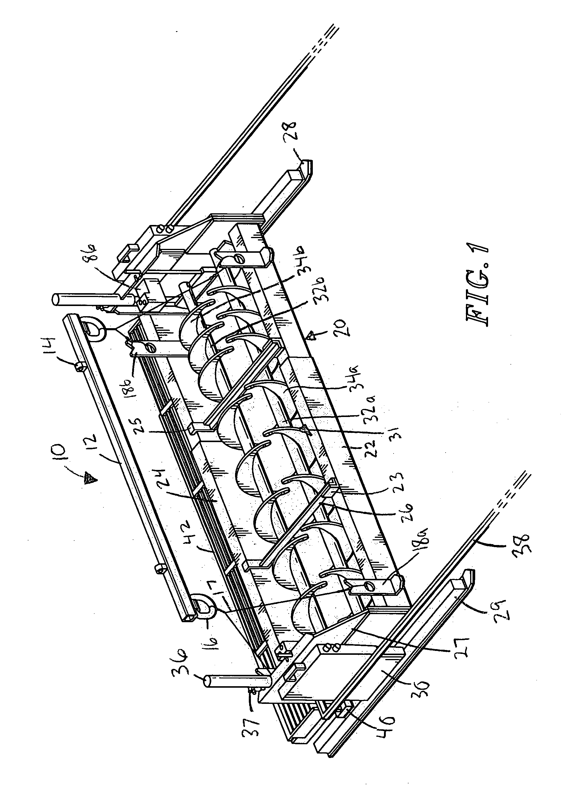
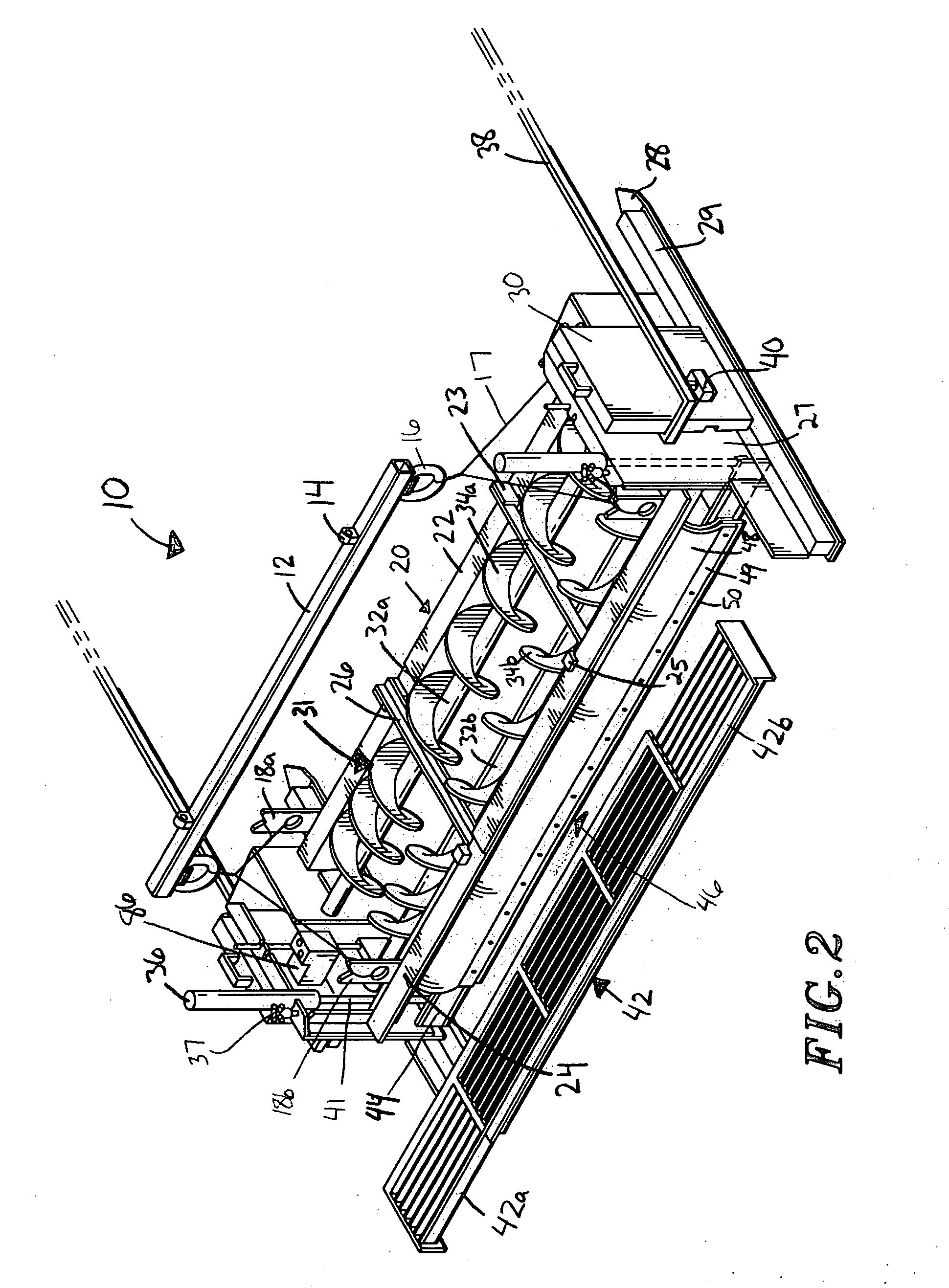
[0016] Referring to FIG. 1, a portable drag box with pugmill for use in applying a paving material to a surface is broadly designated by reference numeral 10. Drag box 10 includes a pull-bar 12, with pull rings 14 located on the upper edge of pull bar 12 and attach rings 16 on the lower edge of pull bar 12. Cables 17 couple attach rings 16 to tie points 18a, 18b on a frame 20 of drag box 10. Frame 20 includes a front bar 22, a rear bar 24, and confinement ends 27. Cross bars 26 extend between front bar 22 and rear bar 24 and provide rigidity to frame 20. Cross bars 26 are secured to front bar 22 via brace 23 and to rear bar 24 via brace 25. The frame 20 is coupled with and rides on skis 28 via its confinement ends 27. Gear boxes 30 are also coupled with skis 28 and confinement ends 27. Skis 28 provide support for gear boxes 30 via support blocks 29. A pugmill is broadly designated by reference numeral 31. It includes two shafts 32a, 32b that extend between gear boxes 30. It further ...


PUM


Abstract

A drag box for use in applying cold mix asphalt paving material to a surface is provided. The drag box includes a pugmill for distributing the cold mix over the surface, a strike blade for shearing the asphalt mixture to a desired thickness, cylinders for raising and lowering the strike blade in response to elevational changes in the surface, at least one signal generator associated with each cylinder and adapted to produce a signal indicative of the elevation of the surface, and at least one signal receiver associated with each signal generator. The drag box is pulled behind a prime mover but preferably is not rigidly coupled with the prime mover. The blade is raised and lowered in response to signals emanating from the generator as the elevation of the surface changes, allowing surface level variations to be evened out while paving.

Description

CROSS-REFERENCE TO RELATED APPLICATIONS [0001] Not Applicable. STATEMENT REGARDING FEDERALLY SPONSORED RESEARCH OR DEVELOPMENT [0002] Not Applicable. BACKGROUND OF THE INVENTION [0003] The present invention relates to a paving apparatus for applying asphalt mixtures to a surface. More specifically, the apparatus is a portable drag box that includes a pugmill and an adjustable strike blade. It is especially useful for applying cold mix. [0004] While screeds are commonly used to smooth hot mix paving material as it is applied, cold mix paving material is typically too viscous for conventional screeds to properly smooth the applied material. The screeds tend to grab and pull the viscous mix as it is being applied. [0005] Conventional adjustment mechanisms for screeds simply change the tilt or angle of attack of the screed but do not raise or lower the screed. Thus, in order to continue to lay a planar surface when the stiffness of the paving mixture increases, the forward speed of the ...

Claims


Application Information

Patent Timeline
IPC IPC(8): E01C19/18E01C23/07
CPCE01C19/187
Inventor GRUBBA, BILL
Owner ARR MAZ PRODS
Learn More